Subaru Legacy BN/BS (2015-2019) Service Manual: Assembly
1. FORWARD CLUTCH ASSEMBLY 1. Install the forward clutch piston to forward clutch drum. NOTE: • Apply CVTF to the seal of forward clutch piston. • Insert it all the way to the end.
2. Install the return spring.
3. Install the chamber COMPL. NOTE: Apply CVTF to the sealing area of chamber COMPL.
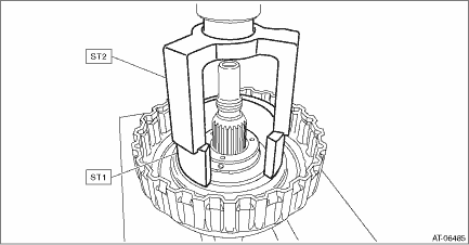
4. Compress the return spring using the ST to install the snap ring.
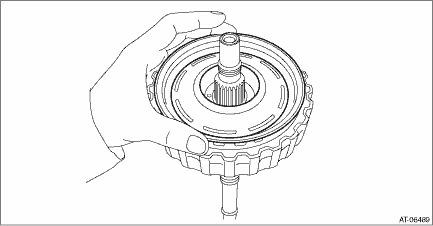
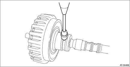
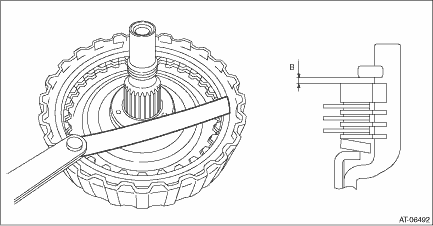
5. Check the operation of forward clutch piston by blowing compressed air intermittently from forward clutch carrier hole.
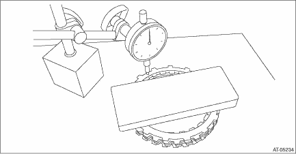
6. Place the driven plate, drive plate and retaining plate neatly in this order on surface table. 7. Set the dial gauge to retaining plate, and read its scale. NOTE: The value, which is read in the gauge at this time, is zero point. 8. Scale and record the weight “Z” of a flat board which will be put on retaining plate. NOTE: • Use a stiff board which does not bend against load as a flat board to be put on retaining plate. • Use a flat board weighing less than 52 N (5.3 kgf, 11.7 lb). 9. Put the flat board on retaining plate.
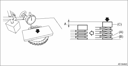
10. Using the following formula, read the push/pull gauge and calculate “N”. N = 52 N (5.3 kgf, 11.7 lb) − Z 52 N (5.3 kgf, 11.7 lb) : Load applied to clutch plate Z: Flat board weight 11. Press the center of retaining plate by applying a force of “N” using push/pull gauge, and then measure and record the compression amount “A”. NOTE: Measure at four points with a 90° interval and calculate the average.
12. Install the dish plate, drive plate, driven plate, retaining plate and snap ring to the forward clutch carrier. NOTE: Install the dish plate in the correct direction.
13. Measure and record the clearance “B” between the retaining plate and snap ring.
14. Piston stroke calculation Calculate with A and B dimensions recorded before. If it exceeds the limit, replace with a new drive plate and adjust within the initial standard value. S mm (in) = A + B S: Piston stroke A: Compression amount of drive plate and dish plate B: Clearance between retaining plate and snap ring Initial standard: 1.0 — 1.4 mm (0.040 — 0.055 in) Limit thickness: 1.6 mm (0.063 in)
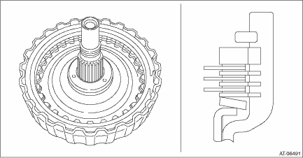
2. PLANETARY CARRIER ASSEMBLY 1. Install the balance oil guide. 2. Install the snap ring. 3. INTERNAL GEAR 1. Install the thrust gear plate. 2. Install the snap ring. | ||||||||||||||||||||||||
 Disassembly
1. FORWARD CLUTCH ASSEMBLY1. Remove the snap ring.2. Remove the retaining plate, drive plate, driven plate and dish plate.3. Compress the return spring using the ST to remove the snap ring.ST1 1876 ...

Other materials:
Dtc p0961 pressure control solenoid "a" control circuit range/performance
DTC DETECTING CONDITION:Immediately at fault recognitionTROUBLE SYMPTOM:• Acceleration is poor during standing start.• Shift control malfunction• Engine speed increases abruptly.1. ENGINE TYPE FBWIRING DIAGRAM:CVT control system CVT Control System > WIRING DIAGRAMSTEPCHECKYESNO1.C ...
