Subaru Legacy BN/BS (2015-2019) Service Manual: Assembly
NOTE: After assembling, manually turn the pulley to check that the rotor rotates smoothly. 1. Use the following procedures to install the rectifier. (1) Remove old silicone grease on the mating surface of rear cover and rectifier and apply new silicone grease. CAUTION: Do not apply silicone grease to the attachment threads of rectifier. (2) Install the rectifier and secure it using bolts. Tightening torque: 3.9 N·m (0.4 kgf-m, 2.9 ft-lb)
(3) Install the nut on terminal B. Tightening torque: 8.9 N·m (0.9 kgf-m, 6.6 ft-lb)
(4) Install the cover on terminal B.
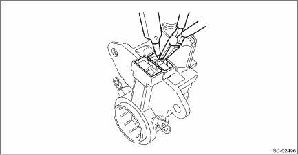
2. Use the following procedures to install the brush. (1) Install the brush and connect the connection.
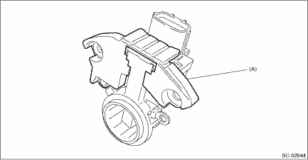
(2) Install the cover B.
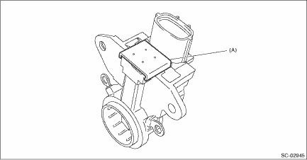
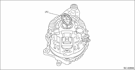
(3) Install the cover A.
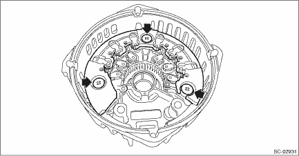
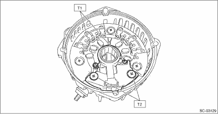
3. Install the IC regulator, and secure it to the rear cover using the four screws. Tightening torque: T1: 2 N·m (0.2 kgf-m, 1.5 ft-lb) T2: 3.9 N·m (0.4 kgf-m, 2.9 ft-lb)
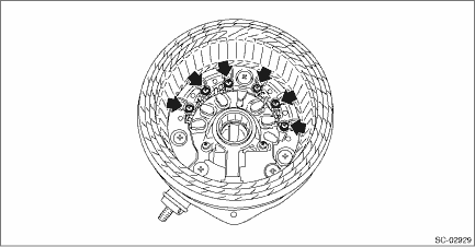
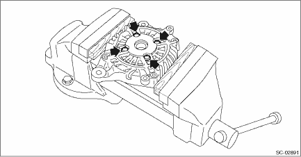
4. Install the stator coil, and secure it together with the rectifier using six bolts. Tightening torque: 2 N·m (0.2 kgf-m, 1.5 ft-lb)
5. Install the ball bearings. (1) Set the ball bearings in the front cover, then securely install an appropriate tool (such as a socket wrench of proper size) to the bearing outer race. (2) Using a press to press the ball bearings into the specified location. (3) Install the bearing retainer. Tightening torque: 3.9 N·m (0.4 kgf-m, 2.9 ft-lb)
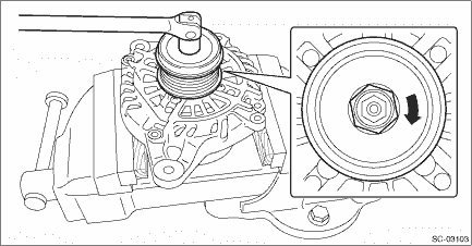
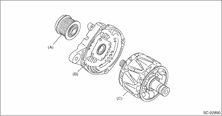
6. Use a press to install the bearings to the rotor shaft. 7. Install the rotor to the front cover, and install the pulley holding the rotor using a vise. CAUTION: When holding the rotor with a vise, place aluminum plates or wooden pieces on the vise jaws to prevent rotor from damage. Tightening torque: 108 N·m (11.0 kgf-m, 79.8 ft-lb)
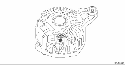
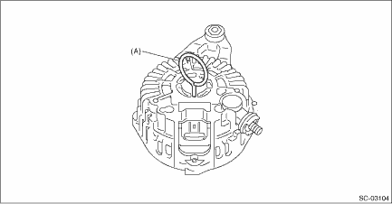
8. Press the brush into the brush holder, then fix the brush in that position by inserting a [1 mm (0.0394 in) dia., 40 — 50 mm (1.5748 — 1.9685 in) long] wire through the hole as shown in the figure.
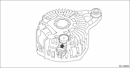
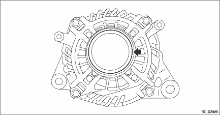
9. Heat the bearing box in rear cover at 50 to 60°C (122 to 140°F), and then press the bearing into rear cover. CAUTION: Do not apply grease to the bearings. If there is any oil on the bearing box, remove it completely. 10. Remove the wire.
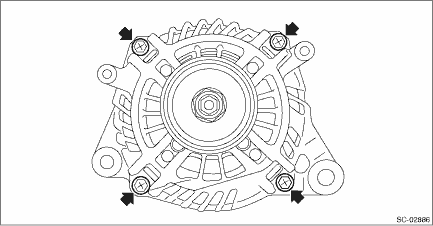
11. Install the four bolts. Tightening torque: 4.4 N·m (0.4 kgf-m, 3.2 ft-lb)
12. Install the cap to the generator.
|
 Removal
1. Disconnect the ground terminal from battery sensor. NOTE2. Remove the V-belts. V-belt > REMOVAL3. Disconnect the connector (A) and terminal (B) from the generator, and remove the clip (C).4. Remo ...
 Installation
1. Temporarily install the generator bracket to the engine and tighten the bolts in the numerical order.Tightening torque:36 N·m (3.7 kgf-m, 26.6 ft-lb)2. Install the V-belt tensioner. V-belt ...
Other materials:
Electrical component location location
1. ENGINE COMPARTMENT(1)Pressure sensor(2)A/C compressor(Refrigerant flow sensor, variable flow change solenoid)(3)Ambient sensor2. PASSENGER COMPARTMENT(1)Evaporator sensor(5)Sunload sensor(9)A/C control panel(2)Air mix door actuator*1 or air mix door actuator LH*2(6)Intake door actuator(10)Air mix ...
