
Subaru Legacy BN/BS (2015-2019) Service Manual: Communication for initializing impossible
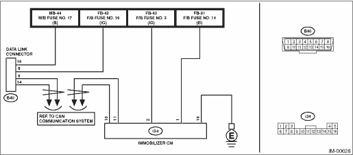
1. ECM If the communication with ECM is not possible, refer to ENGINE (DIAGNOSTICS). Basic Diagnostic Procedure > PROCEDURE Basic Diagnostic Procedure > PROCEDURE 2. BODY INTEGRATED UNIT If the communication with the body integrated unit is not possible, refer to BODY CONTROL SYSTEM (DIAGNOSTICS). Basic Diagnostic Procedure > PROCEDURE 3. IMMOBILIZER CM DETECTING CONDITION: • Defective harness • Power supply circuit malfunction • Defective immobilizer CM • Body integrated unit malfunctioning • Defective CAN communication circuit • Defective Subaru Select Monitor TROUBLE SYMPTOM: Not communicable with Subaru Select Monitor. WIRING DIAGRAM: NOTE: For the coupling connector, refer to “WIRING SYSTEM”. Immobilizer system Immobilizer System > WIRING DIAGRAM
|

 Operation
For operation procedures, refer to “Application help”. ...
Other materials:
Dtc b16b8 short in side satellite sensor bus lh (to +b)
DIAGNOSIS START CONDITION:Ignition voltage is 10 V to 16 V.DTC DETECTING CONDITION:Shorted between side sensor LH circuit and power supply circuitWIRING DIAGRAM:NOTE:For the coupling connector, refer to “WIRING SYSTEM”.Airbag system Airbag System > WIRING DIAGRAMSTEPCHECKYESNO1.CHECK PO ...
