Subaru Legacy BN/BS (2015-2019) Service Manual: Disassembly
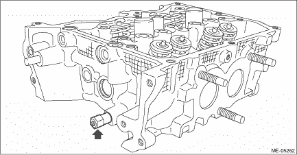
1. Remove the chain cover securing bolt from the cylinder head LH.
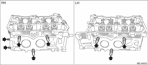
2. Remove the stud bolts from the cylinder head.
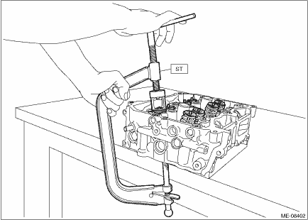
3. Remove the valve collet, valve, valve spring retainer, valve spring and valve spring seat from the cylinder head RH. CAUTION: During work, place a waste cloth, etc. to avoid scratching the mating surface of the cylinder head RH. NOTE: • Mark each part to prevent confusion. • Keep all the removed parts in order for re-installing in their original positions. (1) Compress the valve spring and remove the valve collet using ST.
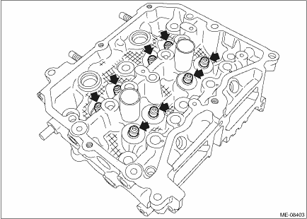
(2) Remove valve, valve spring retainer, valve spring and valve spring seat. 4. Remove the valve collet, valve, valve spring retainer, valve spring and valve spring seat from the cylinder head LH. 5. Remove the valve oil seals from valve guides of cylinder head RH. CAUTION: • During work, place a waste cloth, etc. to avoid scratching the mating surface of the cylinder head RH. • Use special care not to damage the cylinder head RH and guide during work. NOTE: For removal of valve guide, refer to INSPECTION. Cylinder Head > INSPECTION
6. For cylinder head LH, remove the valve oil seal in the same manner. |
 Inspection
1. CYLINDER HEAD1. Visually inspect to make sure that there are no cracks, scratches or other damage.2. Use liquid penetrant tester on the important sections to check for fissures.3. Check that there ...
 Engine assembly
...
Other materials:
Inspection
1. CHECK HORN SWITCHCAUTION:Refer to “CAUTION” of “General Description” before handling the airbag system components. General Description > CAUTION1. Disconnect the ground terminal from the battery sensor, and wait for at least 60 seconds before starting work. NOTE2. Remove ...
