Honda Civic manuals

Subaru Legacy BN/BS (2015-2019) Service Manual: Dtc b1570 antenna

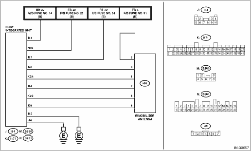
1. EXCEPT FOR C0 AND C5 MODELS

DIAGNOSIS START CONDITION:

Battery voltage is 10 V or more.

The remote engine starter was not used to start the engine.

DTC DETECTING CONDITION:

Received an immobilizer antenna malfunction signal during unit collation

TROUBLE SYMPTOM:

Engine will not start.

The security indicator illuminates.

CAUTION:

When the body integrated unit is replaced, registration of the immobilizer system is required. For details, refer to the “REGISTRATION MANUAL FOR IMMOBILIZER” provided as a separate volume.

WIRING DIAGRAM:

Immobilizer system Immobilizer System > WIRING DIAGRAM

STEPCHECKYESNO

1.CHECK FUSE.

1) Turn the ignition switch to OFF.

2) Check the fuse.

Is there any fault-

Replace the fuse. If the fuse blows out easily, repair the short circuit to power supply in harness between the battery and body integrated unit.

Diagnostic Procedure with Diagnostic Trouble Code (DTC) > DTC B1570 ANTENNA

2.CHECK CURRENT DATA.

Confirm the current data «BATT voltage (control)» display of body integrated unit. Read Current Data

Is the voltage 10 V or more-

Diagnostic Procedure with Diagnostic Trouble Code (DTC) > DTC B1570 ANTENNA

Diagnostic Procedure with Diagnostic Trouble Code (DTC) > DTC B1570 ANTENNA

3.CHECK POWER SUPPLY CIRCUIT FOR IMMOBILIZER ANTENNA.

1) Turn the ignition switch to OFF.

2) Disconnect the connector from immobilizer antenna.

3) Insert the ignition key into the key cylinder, then measure the voltage between the immobilizer antenna connector and the chassis ground using an oscilloscope.

Connector & terminal

(i60) No. 1 (+) — Chassis ground (−):

Is the voltage 5±0.5 V approx. 200 ms after inserting the ignition key into the key cylinder- And then, does the voltage return to 0 V within 2 s-

Diagnostic Procedure with Diagnostic Trouble Code (DTC) > DTC B1570 ANTENNA

Repair the open or short circuit of harness between the body integrated unit connector and immobilizer antenna connector.

4.CHECK IMMOBILIZER ANTENNA GROUND CIRCUIT (OPEN CIRCUIT).

Measure the resistance between immobilizer antenna connector and chassis ground.

Connector & terminal

(i60) No. 7 — Chassis ground:

(i171) No. 4 — (i60) No. 7:

Is the resistance less than 10 --

Diagnostic Procedure with Diagnostic Trouble Code (DTC) > DTC B1570 ANTENNA

Repair the open circuit in harnesses between the body integrated unit connector and the immobilizer antenna connector, and between the body integrated unit connector and the chassis ground.

5.CHECK IMMOBILIZER ANTENNA COMMUNICATION CIRCUIT (OPEN CIRCUIT).

Measure the resistance between the body integrated unit connector and immobilizer antenna connector.

Connector & terminal

(i171) No. 23 — (i60) No. 5:

(i171) No. 3 — (i60) No. 4:

Is the resistance less than 10 --

Diagnostic Procedure with Diagnostic Trouble Code (DTC) > DTC B1570 ANTENNA

Repair or replace the open circuit of harness between the body integrated unit connector and immobilizer antenna connector.

6.CHECK IMMOBILIZER ANTENNA.

1) Connect all connectors.

2) Insert the ignition key in the ignition switch. (OFF or ACC)

3) Read the DTC of the body integrated unit. Read Diagnostic Trouble Code (DTC)

Is DTC B1411 displayed-

Replace the immobilizer antenna. Immobilizer Antenna Diagnostic Procedure with Diagnostic Trouble Code (DTC) > DTC B1570 ANTENNA

Diagnostic Procedure with Diagnostic Trouble Code (DTC) > DTC B1570 ANTENNA

7.CHECK IMMOBILIZER ANTENNA.

1) Insert the ignition key in the ignition switch. (OFF or ACC)

2) Read the DTC of the body integrated unit. Read Diagnostic Trouble Code (DTC)

Is DTC B1411 displayed-

Replace the body integrated unit. Body Integrated Unit

Malfunction occurred in the immobilizer antenna.

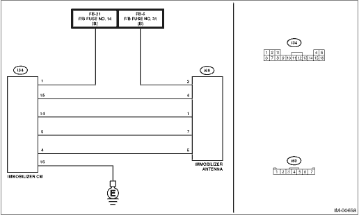
2. FOR C0 AND C5 MODELS

DIAGNOSIS START CONDITION:

Battery voltage is 10 V or more.

The remote engine starter was not used to start the engine.

DTC DETECTING CONDITION:

Immobilizer antenna is faulty.

TROUBLE SYMPTOM:

Engine will not start.

The security indicator illuminates.

CAUTION:

When the immobilizer CM is replaced, registration of the immobilizer system is required. For details, refer to the “REGISTRATION MANUAL FOR IMMOBILIZER” provided as a separate volume.

WIRING DIAGRAM:

Immobilizer system Immobilizer System > WIRING DIAGRAM

STEPCHECKYESNO

1.CHECK FUSE.

1) Turn the ignition switch to OFF.

2) Check the fuse.

Is there any fault-

Replace the fuse. If the fuse blows out easily, repair the short circuit to power supply in harness between the battery and immobilizer CM.

Diagnostic Procedure with Diagnostic Trouble Code (DTC) > DTC B1570 ANTENNA

2.CHECK CURRENT DATA.

Confirm the current data «BATT voltage» display of immobilizer CM. Read Current Data

Is the voltage 10 V or more-

Diagnostic Procedure with Diagnostic Trouble Code (DTC) > DTC B1570 ANTENNA

Diagnostic Procedure with Diagnostic Trouble Code (DTC) > DTC B1570 ANTENNA

3.CHECK POWER SUPPLY CIRCUIT FOR IMMOBILIZER ANTENNA.

1) Turn the ignition switch to OFF.

2) Disconnect the connector from immobilizer antenna.

3) Insert the ignition key into the key cylinder, then measure the voltage between the immobilizer antenna connector and the chassis ground using an oscilloscope.

Connector & terminal

(i60) No. 1 (+) — Chassis ground (−):

Is the voltage 5±0.5 V approx. 200 ms after inserting the ignition key into the key cylinder- And then, does the voltage return to 0 V within 2 s-

Diagnostic Procedure with Diagnostic Trouble Code (DTC) > DTC B1570 ANTENNA

Repair the open or short circuit of harness between the immobilizer CM connector and immobilizer antenna connector.

4.CHECK IMMOBILIZER ANTENNA GROUND CIRCUIT (OPEN CIRCUIT).

Measure the resistance between immobilizer antenna connector and chassis ground.

Connector & terminal

(i60) No. 7 — Chassis ground:

(i34) No. 5 — (i60) No. 7:

(i34) No. 16 — Chassis ground:

Is the resistance less than 10 --

Diagnostic Procedure with Diagnostic Trouble Code (DTC) > DTC B1570 ANTENNA

Repair the open circuit in harnesses between the immobilizer CM connector and the immobilizer antenna connector, and between the immobilizer CM connector and the chassis ground.

5.CHECK IMMOBILIZER ANTENNA COMMUNICATION CIRCUIT (OPEN CIRCUIT).

Measure the resistance between immobilizer CM connector and immobilizer antenna connector.

Connector & terminal

(i34) No. 4 — (i60) No. 5:

(i34) No. 15 — (i60) No. 4:

Is the resistance less than 10 --

Diagnostic Procedure with Diagnostic Trouble Code (DTC) > DTC B1570 ANTENNA

Repair the open circuit of harness between the immobilizer CM connector and immobilizer antenna connector.

6.CHECK IMMOBILIZER ANTENNA.

1) Connect all connectors.

2) Insert the ignition key in the ignition switch. (OFF or ACC)

3) Read the DTC of the immobilizer CM. Read Diagnostic Trouble Code (DTC)

Is DTC B1411 displayed-

Replace the immobilizer antenna. Immobilizer Antenna Diagnostic Procedure with Diagnostic Trouble Code (DTC) > DTC B1570 ANTENNA

Diagnostic Procedure with Diagnostic Trouble Code (DTC) > DTC B1570 ANTENNA

7.CHECK IMMOBILIZER ANTENNA.

1) Insert the ignition key in the ignition switch. (OFF or ACC)

2) Read the DTC of the immobilizer CM. Read Diagnostic Trouble Code (DTC)

Is DTC B1411 displayed-

Replace the immobilizer CM. Immobilizer Control Module

Malfunction occurred in the immobilizer antenna.

Dtc b1572 imm circuit except antenna circuit
1. EXCEPT FOR C0 AND C5 MODELSDIAGNOSIS START CONDITION:• Battery voltage is 10 V or more.• The remote engine starter was not used to start the engine.DTC DETECTING CONDITION:Communication ...

Dtc b1411 immobilizer antenna
NOTE:Refer to DTC B1570 for diagnostic procedure. Diagnostic Procedure with Diagnostic Trouble Code (DTC) > DTC B1570 ANTENNA ...

Other materials:

Dtc b14a7 variable solenoid valve circuit
DTC DETECTING CONDITION:Variable flow change solenoid valve circuit is open or shortedTROUBLE SYMPTOM:Refrigerant pressure cannot be changed.WIRING DIAGRAM:Air conditioning system Air Conditioning System > WIRING DIAGRAMSTEPCHECKYESNO1.CHECK CONNECTOR.1) Check connecting condition of the A/C CM con ...

© 2017-2024 Copyright www.sulegacy.com