Honda Civic manuals

Subaru Legacy BN/BS (2015-2019) Service Manual: Dtc b1572 imm circuit except antenna circuit

1. EXCEPT FOR C0 AND C5 MODELS

DIAGNOSIS START CONDITION:

Battery voltage is 10 V or more.

The remote engine starter was not used to start the engine.

DTC DETECTING CONDITION:

Communication failure between body integrated unit and ECM

TROUBLE SYMPTOM:

Engine will not start.

The security indicator illuminates.

CAUTION:

When the body integrated unit or ECM is replaced, registration of the immobilizer system is required. For details, refer to the “REGISTRATION MANUAL FOR IMMOBILIZER” provided as a separate volume.

WIRING DIAGRAM:

Immobilizer system Immobilizer System > WIRING DIAGRAM

STEPCHECKYESNO

1.CHECK GROUNDING POINT.

Check the grounding point of the engine ground and chassis ground.

Are there any loose connections, any foreign objects caught in the ground lines or contact surface, or any fluid stains-

Remove the foreign matters, and tighten to the specified torque. Then start the engine, and check that the fault was removed. Check DTC Read Diagnostic Trouble Code (DTC), and when DTC B1572 is still displayed, Diagnostic Procedure with Diagnostic Trouble Code (DTC) > DTC B1572 IMM CIRCUIT EXCEPT ANTENNA CIRCUIT

Diagnostic Procedure with Diagnostic Trouble Code (DTC) > DTC B1572 IMM CIRCUIT EXCEPT ANTENNA CIRCUIT

2.CHECK FUSE.

1) Turn the ignition switch to OFF.

2) Check the fuse.

Is there any fault-

Replace the fuse. If the fuse blows out easily, repair the short circuit to power supply in harness between the battery and body integrated unit.

Diagnostic Procedure with Diagnostic Trouble Code (DTC) > DTC B1572 IMM CIRCUIT EXCEPT ANTENNA CIRCUIT

3.CHECK CURRENT DATA.

Confirm the current data «BATT voltage (control)» display of body integrated unit. Read Current Data

Is the voltage 10 V or more-

Diagnostic Procedure with Diagnostic Trouble Code (DTC) > DTC B1572 IMM CIRCUIT EXCEPT ANTENNA CIRCUIT

Diagnostic Procedure with Diagnostic Trouble Code (DTC) > DTC B1572 IMM CIRCUIT EXCEPT ANTENNA CIRCUIT

4.CHECK CURRENT DATA.

Check the current data «Voltage of IGN» display of body integrated unit. Read Current Data

Is the voltage 10 V or more-

Diagnostic Procedure with Diagnostic Trouble Code (DTC) > DTC B1572 IMM CIRCUIT EXCEPT ANTENNA CIRCUIT

Diagnostic Procedure with Diagnostic Trouble Code (DTC) > DTC B1572 IMM CIRCUIT EXCEPT ANTENNA CIRCUIT

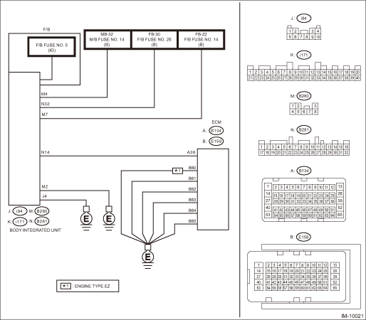
5.CHECK BODY INTEGRATED UNIT BATTERY POWER SUPPLY CIRCUIT.

1) Turn the ignition switch to OFF.

2) Disconnect the body integrated unit connector.

3) Measure the voltage between body integrated unit connector and chassis ground.

Connector & terminal

(B280) No. 4 (+) — Chassis ground (−):

(B280) No. 7 (+) — Chassis ground (−):

(B281) No. 32 (+) — Chassis ground (−):

Is the voltage 10 V or more-

Diagnostic Procedure with Diagnostic Trouble Code (DTC) > DTC B1572 IMM CIRCUIT EXCEPT ANTENNA CIRCUIT

Repair the open or short circuit of harness between the body integrated unit connector and fuse.

6.CHECK BODY INTEGRATED UNIT IGN POWER SUPPLY CIRCUIT.

1) Turn the ignition switch to ON.

2) Measure the voltage between F/B fuse No. 5 and chassis ground.

Connector & terminal

F/B fuse No. 5 (+) — Chassis ground (−):

Is the voltage 10 V or more-

Diagnostic Procedure with Diagnostic Trouble Code (DTC) > DTC B1572 IMM CIRCUIT EXCEPT ANTENNA CIRCUIT

Repair the open or short circuit of harness between the body integrated unit connector and ignition switch.

7.CHECK BODY INTEGRATED UNIT GROUND CIRCUIT (OPEN CIRCUIT).

1) Turn the ignition switch to OFF.

2) Measure the resistance between body integrated unit connector and chassis ground.

Connector & terminal

(B280) No. 2 — Chassis ground:

(i84) No. 4 — Chassis ground:

Is the resistance less than 10 --

Diagnostic Procedure with Diagnostic Trouble Code (DTC) > DTC B1572 IMM CIRCUIT EXCEPT ANTENNA CIRCUIT

Repair the open circuit of harness between the body integrated unit connector and chassis ground.

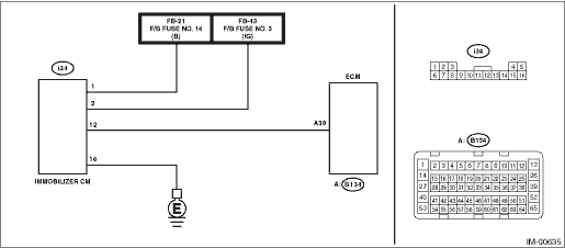
8.CHECK GROUND CIRCUIT FOR ECM (OPEN CIRCUIT).

1) Disconnect the ECM connector.

2) Measure the resistance between the ECM connector and engine ground.

Connector & terminal

(E158) No. 60 — Engine ground (engine type EZ only):

(E158) No. 61 — Engine ground:

(E158) No. 62 — Engine ground:

(E158) No. 63 — Engine ground:

(E158) No. 64 — Engine ground:

(E158) No. 65 — Engine ground:

Is the resistance less than 10 --

Diagnostic Procedure with Diagnostic Trouble Code (DTC) > DTC B1572 IMM CIRCUIT EXCEPT ANTENNA CIRCUIT

Repair the open circuit in harness between ECM connector and chassis ground.

9.CHECK HARNESS (OPEN CIRCUIT) BETWEEN BODY INTEGRATED UNIT AND ECM.

1) Disconnect the ECM connector.

2) Measure the resistance between the body integrated unit connector and ECM.

Connector & terminal

(B281) No. 14 — (B134) No. 38:

Is the resistance less than 10 --

Diagnostic Procedure with Diagnostic Trouble Code (DTC) > DTC B1572 IMM CIRCUIT EXCEPT ANTENNA CIRCUIT

Repair the open circuit of harness between the body integrated unit connector and ECM.

10.CHECK COMMUNICATION LINE HARNESS (SHORT CIRCUIT TO POWER SUPPLY).

1) Disconnect the body integrated unit connector.

2) Turn the ignition switch to ON.

3) Measure the voltage between ECM connector and engine ground.

Connector & terminal

(B134) No. 38 (+) — Chassis ground (−):

Is the voltage 6 V or more-

Repair the short circuit to power supply in harness between body integrated unit connector and ECM connector.

Diagnostic Procedure with Diagnostic Trouble Code (DTC) > DTC B1572 IMM CIRCUIT EXCEPT ANTENNA CIRCUIT

11.CHECK COMMUNICATION CIRCUIT HARNESS (SHORT CIRCUIT TO GROUND).

1) Turn the ignition switch to OFF.

2) Measure the resistance between the ECM connector and each ground.

Connector & terminal

(B134) No. 38 — Chassis ground:

(B134) No. 38 — Engine ground:

Is the resistance less than 10 --

Repair the ground short circuit of harness between body integrated unit connector and ECM connector.

Diagnostic Procedure with Diagnostic Trouble Code (DTC) > DTC B1572 IMM CIRCUIT EXCEPT ANTENNA CIRCUIT

12.CHECK ECM.

1) Replace the ECM. (Do not perform ECM registration.) Engine Control Module (ECM) Engine Control Module (ECM)

2) Connect all connectors.

3) Turn the ignition switch to ON.

4) Wait for 5 seconds.

5) Read DTC of engine. Read Diagnostic Trouble Code (DTC)

Is DTC B1572 displayed-

Replace the body integrated unit. Body Integrated Unit

Register the ECM. Refer to the “REGISTRATION MANUAL FOR IMMOBILIZER” provided as a separate volume.

2. FOR C0 AND C5 MODELS

DIAGNOSIS START CONDITION:

Battery voltage is 10 V or more.

The remote engine starter was not used to start the engine.

DTC DETECTING CONDITION:

Communication failure between immobilizer CM and ECM

TROUBLE SYMPTOM:

Engine will not start.

The security indicator illuminates.

CAUTION:

When the immobilizer CM or ECM is replaced, registration of the immobilizer system is required. For details, refer to the “REGISTRATION MANUAL FOR IMMOBILIZER” provided as a separate volume.

WIRING DIAGRAM:

NOTE:

For the coupling connector, refer to “WIRING SYSTEM”.

Immobilizer system Immobilizer System > WIRING DIAGRAM

STEPCHECKYESNO

1.CHECK GROUNDING POINT.

Check the grounding point of the engine ground and chassis ground.

Are there any loose connections, any foreign objects caught in the ground lines or contact surface, or any fluid stains-

Remove the foreign matters, and tighten to the specified torque. Then start the engine, and check that the fault was removed. Check DTC Read Diagnostic Trouble Code (DTC), and when DTC B1572 is still displayed, Diagnostic Procedure with Diagnostic Trouble Code (DTC) > DTC B1572 IMM CIRCUIT EXCEPT ANTENNA CIRCUIT

Diagnostic Procedure with Diagnostic Trouble Code (DTC) > DTC B1572 IMM CIRCUIT EXCEPT ANTENNA CIRCUIT

2.CHECK FUSE.

1) Turn the ignition switch to OFF.

2) Check the fuse.

Is there any fault-

Replace the fuse. If the fuse blows out easily, repair the short circuit to power supply in harness between the battery and immobilizer CM.

Diagnostic Procedure with Diagnostic Trouble Code (DTC) > DTC B1572 IMM CIRCUIT EXCEPT ANTENNA CIRCUIT

3.CHECK CURRENT DATA.

Confirm the current data «BATT voltage» display of immobilizer system. Read Current Data > OPERATION

Is the voltage 10 V or more-

Diagnostic Procedure with Diagnostic Trouble Code (DTC) > DTC B1572 IMM CIRCUIT EXCEPT ANTENNA CIRCUIT

Diagnostic Procedure with Diagnostic Trouble Code (DTC) > DTC B1572 IMM CIRCUIT EXCEPT ANTENNA CIRCUIT

4.CHECK GROUND CIRCUIT FOR ECM (OPEN CIRCUIT).

1) Disconnect the ECM connector.

2) Measure the resistance between the ECM connector and engine ground.

Connector & terminal

(E158) No. 60 — Engine ground (engine type EZ only):

(E158) No. 61 — Engine ground:

(E158) No. 62 — Engine ground:

(E158) No. 63 — Engine ground:

(E158) No. 64 — Engine ground:

(E158) No. 65 — Engine ground:

Is the resistance less than 10 --

Diagnostic Procedure with Diagnostic Trouble Code (DTC) > DTC B1572 IMM CIRCUIT EXCEPT ANTENNA CIRCUIT

Repair the open circuit in harness between ECM connector and chassis ground.

5.CHECK IMMOBILIZER CM BATTERY POWER SUPPLY CIRCUIT.

1) Turn the ignition switch to OFF.

2) Disconnect the immobilizer CM connector.

3) Measure the voltage between immobilizer CM connector and chassis ground.

Connector & terminal

(i34) No. 1 (+) — Chassis ground (−):

Is the voltage 10 V or more-

Diagnostic Procedure with Diagnostic Trouble Code (DTC) > DTC B1572 IMM CIRCUIT EXCEPT ANTENNA CIRCUIT

Repair the open or short circuit of harness between the immobilizer CM connector and fuse.

6.CHECK IMMOBILIZER CM IGN POWER SUPPLY CIRCUIT.

1) Turn the ignition switch to ON.

2) Measure the voltage between immobilizer CM connector and chassis ground.

Connector & terminal

(i34) No. 2 (+) — Chassis ground (−):

Is the voltage 10 V or more-

Diagnostic Procedure with Diagnostic Trouble Code (DTC) > DTC B1572 IMM CIRCUIT EXCEPT ANTENNA CIRCUIT

Repair the open or short circuit of harness between the immobilizer CM connector and ignition switch.

7.CHECK IMMOBILIZER CM GROUND CIRCUIT (OPEN CIRCUIT).

1) Turn the ignition switch to OFF.

2) Measure the resistance between immobilizer CM connector and chassis ground.

Connector & terminal

(i34) No. 16 — Chassis ground:

Is the resistance less than 10 --

Diagnostic Procedure with Diagnostic Trouble Code (DTC) > DTC B1572 IMM CIRCUIT EXCEPT ANTENNA CIRCUIT

Repair the open circuit of harness between the immobilizer CM connector and chassis ground.

8.CHECK HARNESS BETWEEN IMMOBILIZER CM AND ECM (OPEN CIRCUIT).

Measure the resistance between immobilizer CM connector and ECM connector.

Connector & terminal

(i34) No. 12 — (B134) No. 38:

Is the resistance less than 10 --

Diagnostic Procedure with Diagnostic Trouble Code (DTC) > DTC B1572 IMM CIRCUIT EXCEPT ANTENNA CIRCUIT

Repair the open circuit of harness between the immobilizer CM connector and ECM.

9.CHECK COMMUNICATION LINE HARNESS (SHORT CIRCUIT TO POWER SUPPLY).

1) Turn the ignition switch to ON.

2) Measure the voltage between ECM connector and engine ground.

Connector & terminal

(B134) No. 38 (+) — Engine ground (−):

Is the voltage 6 V or more-

Repair the short circuit to power supply in harness between immobilizer CM connector and ECM connector.

Diagnostic Procedure with Diagnostic Trouble Code (DTC) > DTC B1572 IMM CIRCUIT EXCEPT ANTENNA CIRCUIT

10.CHECK COMMUNICATION CIRCUIT HARNESS (SHORT CIRCUIT TO GROUND).

1) Turn the ignition switch to OFF.

2) Measure the resistance between immobilizer CM connector and each ground.

Connector & terminal

(i34) No. 12 — Chassis ground:

(i34) No. 12 — Engine ground:

Is the resistance less than 10 --

Repair the short circuit to ground in harness between immobilizer CM connector and ECM connector.

Diagnostic Procedure with Diagnostic Trouble Code (DTC) > DTC B1572 IMM CIRCUIT EXCEPT ANTENNA CIRCUIT

11.CHECK ECM.

1) Replace the ECM. (Do not perform ECM registration.) Engine Control Module (ECM) Engine Control Module (ECM)

2) Connect all connectors.

3) Turn the ignition switch to ON.

4) Wait for 5 seconds.

5) Read DTC of engine. Read Diagnostic Trouble Code (DTC)

Is DTC B1572 displayed-

Replace the immobilizer CM. Immobilizer Control Module

Malfunction occurred in ECM. Register the ECM. Refer to the “REGISTRATION MANUAL FOR IMMOBILIZER” provided as a separate volume.

Dtc b1574 key communication
1. EXCEPT FOR C0 AND C5 MODELSDIAGNOSIS START CONDITION:• Battery voltage is 10 V or more.• The remote engine starter was not used to start the engine.DTC DETECTING CONDITION:Communication ...

Dtc b1570 antenna
1. EXCEPT FOR C0 AND C5 MODELSDIAGNOSIS START CONDITION:• Battery voltage is 10 V or more.• The remote engine starter was not used to start the engine.DTC DETECTING CONDITION:Received an i ...

Other materials:

Dtc p05a0 active grille air shutter "a" stuck on
DTC DETECTING CONDITION:Detected when two consecutive driving cycles with fault occur.CAUTION:After servicing or replacing faulty parts, perform Clear Memory Mode Clear Memory Mode > OPERATION, and Inspection Mode Inspection Mode > PROCEDURE.STEPCHECKYESNO1.CHECK ACTIVE GRILLE SHUTTER.Check the ar ...

© 2017-2024 Copyright www.sulegacy.com