1.CHECK FUSE. 1) Turn the ignition switch to OFF. 2) Check the M/B fuse No. 26. | | Diagnostic Procedure with Diagnostic Trouble Code (DTC) > DTC P0717 INPUT/TURBINE SHAFT SPEED SENSOR "A" CIRCUIT NO SIGNAL | Replace the fuse. If the fuse blows out easily, repair the short circuit of harness. |
2.CHECK ECM CONNECTOR. Check the connecting condition of ECM connector. | Is the ECM connector correctly connected- | Diagnostic Procedure with Diagnostic Trouble Code (DTC) > DTC P0717 INPUT/TURBINE SHAFT SPEED SENSOR "A" CIRCUIT NO SIGNAL | Connect the ECM connector correctly. |
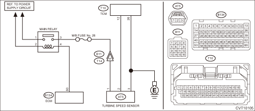
3.CHECK HARNESS BETWEEN TRANSMISSION CONNECTOR AND MAIN RELAY CONNECTOR. 1) Turn the ignition switch to OFF. 2) Measure the voltage between transmission connector and engine ground. Connector & terminal (B11) No. 6 (+) — Engine ground (−): | Is the voltage 10 V or more- | Repair the harness and connector. NOTE: In this case, repair the following item: • Short circuit to power supply of harness between transmission connector and main relay connector • Defective main relay | Diagnostic Procedure with Diagnostic Trouble Code (DTC) > DTC P0717 INPUT/TURBINE SHAFT SPEED SENSOR "A" CIRCUIT NO SIGNAL |
4.CHECK HARNESS BETWEEN ECM AND MAIN RELAY CONNECTOR. 1) Turn the ignition switch to OFF. 2) Remove the main relay. 3) Disconnect the connector from ECM. 4) Measure the resistance between the ECM connector and engine ground. Connector & terminal (B134) No. 60 — Engine ground: | Is the resistance 1 M- or more- | Diagnostic Procedure with Diagnostic Trouble Code (DTC) > DTC P0717 INPUT/TURBINE SHAFT SPEED SENSOR "A" CIRCUIT NO SIGNAL | Repair the short circuit to ground in harness between ECM connector and main relay connector. |
5.CHECK HARNESS. 1) Turn the ignition switch to OFF. 2) Disconnect the TCM and turbine speed sensor connector. 3) Measure the resistance between TCM connector and turbine speed sensor connector. Connector & terminal (T10) No. 12 — (AT5) No. 2: (T10) No. 26 — (AT5) No. 3: | Is the resistance less than 1 -- | Diagnostic Procedure with Diagnostic Trouble Code (DTC) > DTC P0717 INPUT/TURBINE SHAFT SPEED SENSOR "A" CIRCUIT NO SIGNAL | Repair the open circuit of harness. |
6.CHECK HARNESS. Measure the resistance between TCM connector and chassis ground. Connector & terminal (T10) No. 12 — Chassis ground: | Is the resistance 1 M- or more- | Diagnostic Procedure with Diagnostic Trouble Code (DTC) > DTC P0717 INPUT/TURBINE SHAFT SPEED SENSOR "A" CIRCUIT NO SIGNAL | Repair the short circuit of harness. |
7.CHECK TRANSMISSION HARNESS. 2) Connect the TCM connector. 3) Disconnect the transmission connector. 4) Turn the ignition switch to ON. 5) Measure the voltage between transmission connector terminals. Connector & terminal (B11) No. 6 (+) — Chassis ground (−): | Is the voltage 10 — 13 V- | Diagnostic Procedure with Diagnostic Trouble Code (DTC) > DTC P0717 INPUT/TURBINE SHAFT SPEED SENSOR "A" CIRCUIT NO SIGNAL | Repair the open circuit of harness or poor contact of connector. |
8.CHECK INPUT SIGNAL FOR TCM. 1) Turn the ignition switch to OFF. 2) Connect all connectors. 5) Read the data of «Turbine Revolution Speed» using the Subaru Select Monitor. | Does the value of «Turbine Revolution Speed» change according to the engine speed- | Current condition is normal. Repair the poor contacts of harnesses of turbine speed sensor and transmission connector. | Diagnostic Procedure with Diagnostic Trouble Code (DTC) > DTC P0717 INPUT/TURBINE SHAFT SPEED SENSOR "A" CIRCUIT NO SIGNAL |
9.CHECK TRANSMISSION HARNESS. 1) Turn the ignition switch to OFF. 2) Disconnect the transmission connector. 3) Disconnect the turbine speed sensor connector. 4) Measure the resistance between transmission connector and turbine speed sensor connector. Connector & terminal (T14) No. 6 — (AT5) No. 1: | Is the resistance less than 1 -- | Diagnostic Procedure with Diagnostic Trouble Code (DTC) > DTC P0717 INPUT/TURBINE SHAFT SPEED SENSOR "A" CIRCUIT NO SIGNAL | Replace the transmission harness. |
10.CHECK TURBINE SPEED SENSOR. 1) Turn the ignition switch to OFF. 2) Replace the turbine speed sensor. Turbine Speed Sensor 3) Perform the Clear Memory Mode. Clear Memory Mode | | Diagnostic Procedure with Diagnostic Trouble Code (DTC) > DTC P0717 INPUT/TURBINE SHAFT SPEED SENSOR "A" CIRCUIT NO SIGNAL | The original turbine speed sensor is defective. |
11.CHECK MAIN RELAY. 1) Turn the ignition switch to OFF. 2) Replace the main relay. 3) Perform the Clear Memory Mode. Clear Memory Mode | | Replace the TCM. Transmission Control Module (TCM) | The original main relay is defective. |
 Dtc u1433 invalid data received from eyesight
 Dtc u1235 lost communication with eyesight