Subaru Legacy BN/BS (2015-2019) Service Manual: Dtc p2530 ignition switch run position circuit
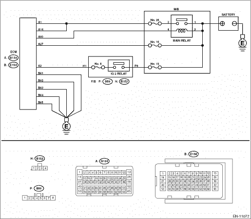
DTC DETECTING CONDITION: Immediately at fault recognition TROUBLE SYMPTOM: Improper idling CAUTION: After servicing or replacing faulty parts, perform Clear Memory Mode Clear Memory Mode > OPERATION, and Inspection Mode Inspection Mode > PROCEDURE. WIRING DIAGRAM: • Engine Electrical System ENGINE TYPE FB (WITHOUT PUSH BUTTON START) Engine Electrical System > WIRING DIAGRAM • Engine Electrical System ENGINE TYPE FB (WITH PUSH BUTTON START) Engine Electrical System > WIRING DIAGRAM
1. OUTLINE OF DIAGNOSIS Detect instantaneous open in ignition switch input circuit to ECM. Judge as NG if out of specification. 2. COMPONENT DESCRIPTION ECM monitors the voltage of the ignition switch input circuit. Judge as ignition switch ON when the voltage is the specified value or more. 3. EXECUTION CONDITION
4. GENERAL DRIVING CYCLE Perform the diagnosis continuously after the enable conditions have been established. 5. DIAGNOSTIC METHOD Judge as NG when the following conditions are established within the predetermined time.
Time Needed for Diagnosis: 5000 ms Malfunction Indicator Light Illumination: Illuminates as soon as a malfunction occurs. |
 Dtc p2610 ecm/pcm engine off timer performance
DTC DETECTING CONDITION:Detected when two consecutive driving cycles with fault occur.CAUTION:After servicing or replacing faulty parts, perform Clear Memory Mode Clear Memory Mode > OPERATION, and I ...
 Dtc p2420 evap system switching valve control circuit high
DTC DETECTING CONDITION:Immediately at fault recognitionCAUTION:After servicing or replacing faulty parts, perform Clear Memory Mode Clear Memory Mode > OPERATION, and Inspection Mode Inspection Mod ...
Other materials:
Assembly
1. Install the O-ring to plug and install the plug to drive pinion retainer.NOTE:• Use new O-rings.• Apply CVTF to the O-rings.Tightening torque:25 N·m (2.5 kgf-m, 18.4 ft-lb)2. Using the ST, install the oil seal to drive pinion retainer.NOTE:• Apply CVTF to the oil seal pre ...
