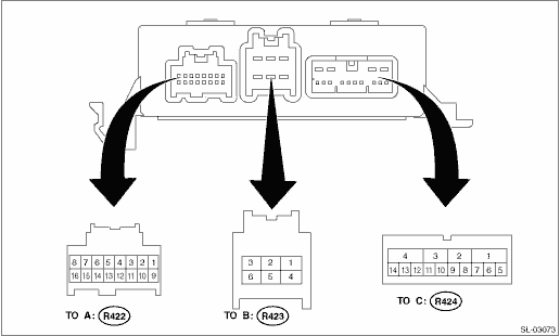
(R422) No. 1 ←> (R422) No. 9 | Touch sensor | When sensor is ON | 2.7 V or less |
(R422) No. 2 ←> Chassis ground | — | — | — |
(R422) No. 3 ←> (R422) No. 9 | Latch switch | When rear gate is fully closed | 9 — 16 V |
(R422) No. 4 ←> (R422) No. 9 | Courtesy switch | When rear gate is fully closed | 9 — 16 V |
(R422) No. 5 ←> (R422) No. 9 | Sector switch | When rear gate is fully closed | Less than 1 V |
(R422) No. 6 ←> (R422) No. 9 | PRG inner SW | When power rear gate inner switch is ON | Less than 1 V |
(R422) No. 7 | — | — | — |
(R422) No. 8 ←> Chassis ground | Memory height switch | When memory height switch is ON | Less than 1 V |
(R422) No. 9 | Switch GND | — | — |
(R422) No. 10 | LIN communication line | — | — |
(R422) No. 11 | — | — | — |
(R422) No. 12 ←> Chassis ground | Ignition SW | When ignition switch is ON | — |
(R422) No. 13 ←> Chassis ground | Power rear gate driver’s switch | When driver’s switch is ON | Less than 1 V |
(R422) No. 14 ←> Chassis ground | — | — | — |
(R422) No. 15 ←> Chassis ground | Hazard output | When hazard is not operating | Less than 1 V |
(R422) No. 16 ←> Chassis ground | — | — | — |
(R423) No. 1 ←> Chassis ground | Battery power supply (+POWER B) | Always | 9 — 16 V |
(R423) No. 2 ←> Chassis ground | Closer (CLOSE) | When the power rear gate auto closer is performing the pull-in operation | 9 — 16 V |
(R423) No. 3 ←> Chassis ground | Closer (OPEN) | When power rear gate auto closer is performing the release operation | 9 — 16 V |
(R423) No. 4 ←> Chassis ground | GND | Always | Less than 1 - |
(R423) No. 5 ←> Chassis ground | — | — | — |
(R423) No. 6 ←> Chassis ground | Battery power supply (+B) | Always | 9 — 16 V |
(R424) No. 1 ←> Chassis ground | — | — | — |
(R424) No. 2 ←> Chassis ground | — | — | — |
(R424) No. 3 ←> Chassis ground | Motor (CLOSE) | When auto-closing is in operation | Pulse |
(R424) No. 4 ←> Chassis ground | Motor (OPEN) | When auto-open is in operation | Pulse |
(R424) No. 5 | Buzzer (−) | — | — |
(R424) No. 6 ←> (R424) No. 5 | Buzzer (+) | When buzzer sounds | Pulse |
(R424) No. 7 ←> Chassis ground | — | — | — |
(R424) No. 8 ←> Chassis ground | HALL RETURN | — | — |
(R424) No. 9 ←> (R424) No. 8 | HALL2 | — | — |
(R424) No. 10 ←> (R424) No. 8 | HALL1 | — | — |
(R424) No. 11 ←> Chassis ground | HALL FEED | — | — |
(R424) No. 12 ←> Chassis ground | — | — | — |
(R424) No. 13 ←> Chassis ground | — | — | — |
(R424) No. 14 ←> Chassis ground | — | — | — |
 Wiring diagram
