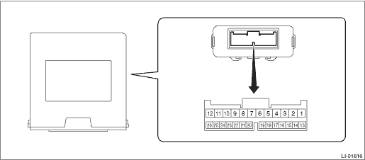
1 ←> Chassis ground | Battery power supply (right) | Always | 8 — 16 V |
2 ←> Chassis ground | — | — | — |
3 ←> Chassis ground | Fog light output (right) | Fog light switch ON | 8 — 16 V |
4 ←> Chassis ground | — | — | — |
5 ←> Chassis ground | SRF OFF switch | SRF OFF switch OFF > ON | 5 V or more > 1.5 V or less |
6 ←> Chassis ground | — | — | — |
7 ←> Chassis ground | — | — | — |
8 ←> Chassis ground | Rear vehicle height sensor signal*1 | IG ON (with no passenger, no load and vehicle stopped) | Approx. 2.5 V (changes according to vehicle condition) |
9 ←> Chassis ground | — | — | — |
10 ←> Chassis ground | Fog light output (left) | Fog light switch ON | 8 — 16 V |
11 ←> Chassis ground | — | — | — |
12 ←> Chassis ground | Battery power supply (left) | Always | 8 — 16 V |
13 ←> Chassis ground | GND | Always | Less than 1 - |
14 ←> Chassis ground | Ignition power supply | Ignition switch ON | 8 — 16 V |
15 ←> Chassis ground | Leveling actuator power supply*1 | Ignition switch ON | 8 — 16 V |
16 ←> Chassis ground | Leveling actuator GND*1 | Always | Less than 1 - |
17 ←> Chassis ground | — | — | — |
18 ←> Chassis ground | — | — | — |
19 ←> Chassis ground | — | — | — |
20 ←> Chassis ground | — | — | — |
21 ←> Chassis ground | Leveling actuator signal*1 | Headlight off > on | Less than 1 V > 1.0 — 14.4 V (for 17 seconds) |
Headlight on, no vehicle height change > change and hold vehicle height for 3 seconds or more |
22 ←> Chassis ground | — | — | — |
23 ←> Chassis ground | Rear vehicle height sensor power supply*1 | Ignition switch ON | 4.75 — 5.25 V |
24 ←> Chassis ground | Rear vehicle height sensor GND*1 | Always | Less than 1 - |
25 ←> Chassis ground | CAN-H (CAN communication line) | Cannot be measured | — |
26 ←> Chassis ground | CAN-L (CAN communication line) | Cannot be measured | — |
 Wiring diagram
