
Subaru Legacy BN/BS (2015-2019) Service Manual: Inspection
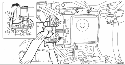
1. CRANKSHAFT POSITION SENSOR 1. Disconnect the ground terminal from battery sensor. NOTE 2. Prepare an oscilloscope. 3. While pressing the section (A) shown in the figure, move the lock lever (B) in the direction of the arrow to disconnect the connectors from the ECM in numerical order as shown in the figure.
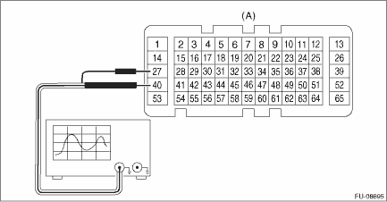
4. Attach the ST between the ECM, engine harness and the bulkhead wiring harness. General Description > CAUTION
5. Connect the probe to ST.
6. Start the engine and let it idle. 7. Check the waveforms and voltage. NOTE: For waveform and voltage, refer to “Engine Control Module (ECM) I/O Signal”. Engine Control Module (ECM) I/O Signal > ELECTRICAL SPECIFICATION 8. After inspection, install the related parts in the reverse order of removal. 2. OTHER INSPECTIONS Check that the crankshaft position sensor has no deformation, cracks or other damages. |
 Removal
1. Disconnect the ground terminal from battery sensor. NOTE2. Remove the clip (A), and loosen the clamps (B) and (C) securing the air intake boot.3. Remove the air intake boot from the air cleaner ca ...
 Installation
1. Install the crankshaft position sensor to the cylinder block, and connect the connector to the crankshaft position sensor.Tightening torque:6.4 N·m (0.7 kgf-m, 4.7 ft-lb)2. Install the air i ...
Other materials:
Dtc b1012 battery backup power supply
DTC DETECTING CONDITION:Voltage failure caused by poor contact of battery power supply backup circuitsBAT (back-up) voltage was outside the range of 8.3 — 16.7 V, when the BAT (back-up) power supply was ON.Time Needed for Diagnosis:40 s or moreTROUBLE SYMPTOM:Illuminations for the keyless entry, m ...
