Subaru Legacy BN/BS (2015-2019) Service Manual: Inspection
1. ACTUATOR LINK 1. Visually check the operating range of the link, and remove the foreign matter if any. 2. Operate the temperature control switch, and check that the link operates normally. 3. If it does not operate normally as the result of inspection, perform a unit inspection of motor assembly - rear heater. 2. CHECK ACTUATOR OPERATION 1. Check the actuator operation when battery voltage is applied between the connector terminals. CAUTION: Disconnect the battery immediately after the actuator stops operation. Otherwise, the motor may be damaged.
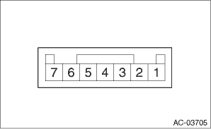
2. Measure the resistance between connector terminals. Preparation tool: Circuit tester
3. Connect the connector, turn the ignition switch to ON, and check the voltage between actuator terminals.
4. Replace the motor assembly - rear heater if faulty is found in the inspection. |
 Removal
CAUTION:Before handling the airbag system components, refer to “CAUTION” of “General Description” in “AIRBAG SYSTEM”. General Description > CAUTION1. Disconnect th ...
 Installation
CAUTION:Before handling the airbag system components, refer to “CAUTION” of “General Description” in “AIRBAG SYSTEM”. General Description > CAUTION1. Install the m ...
Other materials:
If your vehicle is involved in an accident
CAUTION
If your vehicle is involved in an
accident, be sure to inspect the
ground under the vehicle before
restarting the engine. If you find that
fuel has leaked on the ground, do
not try to restart the engine. The fuel
system has been damaged and is in
need of repair ...
