Subaru Legacy BN/BS (2015-2019) Service Manual: Inspection
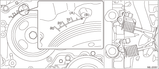
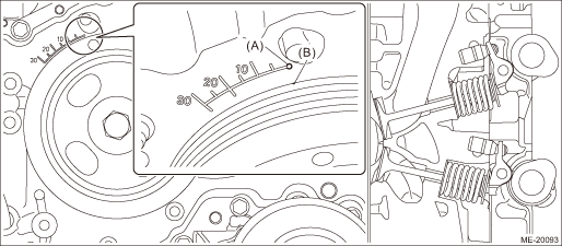
1. WHEN TIMING CHAIN ASSEMBLY IS NOT REMOVED CAUTION: When working on the vehicle, if engine oil is spilt onto the exhaust pipe, wipe it off with cloth to avoid emission of smoke or causing a fire. NOTE: • Inspection of cam clearance should be performed while engine is cold. • If the engine is removed from vehicle, performing the step 1) is not necessary. 1. Remove the air intake duct. Air Intake Duct > REMOVAL 2. Remove the V-belts. V-belt > REMOVAL 3. When inspecting #1 and #3 cylinders (1) Remove the rocker cover RH. Rocker Cover > REMOVAL NOTE: When working on the vehicle, place a suitable container under the vehicle. (2) Set #1 cylinder piston to top dead center of compression stroke by rotating the crank pulley clockwise using the socket wrench. NOTE: When the timing mark (B) on crank pulley is aligned to the 0° in timing gauge (A) on chain cover as shown in the figure, the #1 cylinder piston is located at TDC of compression stroke if the intake camshaft and exhaust camshaft does not depress the #1 cylinder intake side roller rocker arm (intake valve) and exhaust side roller rocker arm (exhaust valve). If roller rocker arm (valve) is depressed, turn the crank pulley by 360° in order to make #1 cylinder piston at TDC of compression stroke.
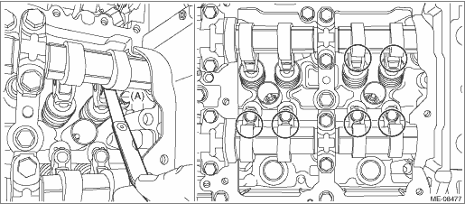
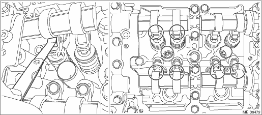
(3) Check the cam clearance for #1 cylinder intake, #1 cylinder exhaust and #3 cylinder exhaust. NOTE: • Measure the roller surface of cam base circle and roller rocker arm using thickness gauge (A). • If the measured value is out of standard, take notes of the value in order to adjust the cam clearance later on. Cam clearance: Intake Standard Exhaust Standard
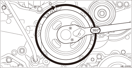
(4) Turn the crank pulley by 360°.
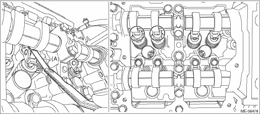
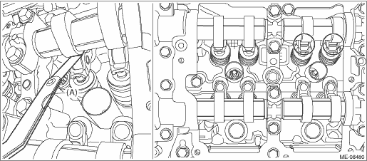
(5) Check the clearance of #3 cylinder intake. NOTE: • Measure the roller surface of cam base circle and roller rocker arm using thickness gauge (A). • If the measured value is out of standard, take notes of the value in order to adjust the cam clearance later on. Cam clearance: Standard 0.13+0.02 −0.03 mm (0.0051+0.0008 −0.0012 in)
4. When inspecting #2 and #4 cylinders (1) Remove the rocker cover LH. Rocker Cover > REMOVAL NOTE: When working on the vehicle, place a suitable container under the vehicle. (2) Set #2 cylinder piston to top dead center of compression stroke by rotating the crank pulley clockwise using the socket wrench. NOTE: When the timing mark (B) on crank pulley is aligned to the 0° in timing gauge (A) on chain cover as shown in the figure, the #2 cylinder piston is located at TDC of compression stroke if the intake camshaft and exhaust camshaft does not depress the #2 cylinder intake side roller rocker arm (intake valve) and exhaust side roller rocker arm (exhaust valve). If roller rocker arm (valve) is depressed, turn the crank pulley by 360° in order to make #2 cylinder piston at TDC of compression stroke.
(3) Check the cam clearance for #2 cylinder intake, #2 cylinder exhaust and #4 cylinder exhaust. NOTE: • Measure the roller surface of cam base circle and roller rocker arm using thickness gauge (A). • If the measured value is out of standard, take notes of the value in order to adjust the cam clearance later on. Cam clearance: Intake Standard Exhaust Standard
(4) Turn the crank pulley by 360°.
(5) Check the clearance of #4 cylinder intake. NOTE: • Measure the roller surface of cam base circle and roller rocker arm using thickness gauge (A). • If the measured value is out of standard, take notes of the value in order to adjust the cam clearance later on. Cam clearance: Standard 0.13+0.02 −0.03 mm (0.0051+0.0008 −0.0012 in)
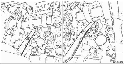
5. If necessary, adjust the cam clearance. Cam Clearance > ADJUSTMENT 6. After inspection, install the related parts in the reverse order of removal. 2. WHEN TIMING CHAIN ASSEMBLY IS REMOVED NOTE: Inspection of cam clearance should be performed while engine is cold. 1. When inspecting #1 and #3 cylinders (1) Remove the rocker cover RH. Rocker Cover > REMOVAL NOTE: When working on the vehicle, place a suitable container under the vehicle. (2) Check the #1 and #3 cylinder cam clearance. CAUTION: Intake and exhaust camshafts can be independently rotated with the timing chain removed. When the intake valve and exhaust valve lift at the same time, the valve heads contact each other and valve stem may bend. Do not turn it to the outside of range of zero lift (cam base circle position) (in range where it can be turned lightly by hand). NOTE: • For cam clearance inspection, adjust the cam base circle position so that the thickness gauge (A) can be inserted easily by hand turning the camshaft (cam sprocket) to be measured. • Measure the roller surface of cam base circle and roller rocker arm using thickness gauge (A). • If the measured value is out of standard, take notes of the value in order to adjust the cam clearance later on. Cam clearance: Intake Standard Exhaust Standard
2. When inspecting #2 and #4 cylinders (1) Remove the rocker cover LH. Rocker Cover > REMOVAL NOTE: When working on the vehicle, place a suitable container under the vehicle. (2) Check the #2 and #4 cylinder cam clearance. CAUTION: Intake and exhaust camshafts can be independently rotated with the timing chain removed. When the intake valve and exhaust valve lift at the same time, the valve heads contact each other and valve stem may bend. Do not turn it to the outside of range of zero lift (cam base circle position) (in range where it can be turned lightly by hand). NOTE: • For cam clearance inspection, adjust the cam base circle position so that the thickness gauge (A) can be inserted easily by hand turning the camshaft (cam sprocket) to be measured. • Measure the roller surface of cam base circle and roller rocker arm using thickness gauge (A). • If the measured value is out of standard, take notes of the value in order to adjust the cam clearance later on. Cam clearance: Intake Standard Exhaust Standard
3. If necessary, adjust the cam clearance. Cam Clearance > ADJUSTMENT 4. After inspection, install the related parts in the reverse order of removal. |

 Cam clearance
...
 Adjustment
1. Remove the engine from the vehicle. Engine Assembly > REMOVAL2. Remove the chain cover. Chain Cover > REMOVAL3. When adjusting #1 and #3 cylinders(1) Remove the timing chain RH. Timing Chain Ass ...
Other materials:
Dtc p2103 throttle actuator "a" control motor circuit high
DTC DETECTING CONDITION:Immediately at fault recognitionCAUTION:After servicing or replacing faulty parts, perform Clear Memory Mode Clear Memory Mode > OPERATION, and Inspection Mode Inspection Mode > PROCEDURE.WIRING DIAGRAM:• Engine Electrical System ENGINE TYPE EZ (WITHOUT PUSH BUTTON ST ...
