
Subaru Legacy BN/BS (2015-2019) Service Manual: Inspection
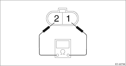
1. PURGE CONTROL SOLENOID VALVE 1. Check that the purge control solenoid valve has no deformation, cracks or other damages. 2. Measure the resistance between the purge control solenoid valve terminals.
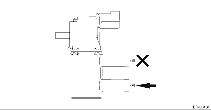
3. Check that air does not come out from (B) when air is blown into (A).
4. Connect the battery positive terminal to the terminal No. 1 and the battery negative terminal to the terminal No. 2. Check that air is discharged from (B), when supplying air to (A).
2. OTHER INSPECTIONS Check the vacuum hose for cracks, damage or looseness. |

 Removal
1. Remove the collector cover.(1) Carefully pull up the rear of collector cover at two positions (A).(2) Carefully pull up the front of collector cover at two positions (B) while moving it forward.2. ...
 Installation
1. Install the purge control solenoid valve, and connect the connector and vacuum hose to the purge control solenoid valve.NOTE:Connect the vacuum hose as shown in the figure.(a)To intake manifold(b)T ...
Other materials:
General diagnostic table inspection
SymptomsFaulty partsTire pressure warning light illuminates.Tire pressure is reduced.• Improper tire pressure adjustment• Punctured tireTire pressure warning light blinks 25 times and then illuminates.Tire pressure monitoring system has malfunction.• Air pressure sensor malfunction ...
