Subaru Legacy BN/BS (2015-2019) Service Manual: Inspection
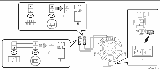
1. VISUAL INSPECTION Check for the following, and replace the damaged parts with new parts. • Combination switch is cracked or deformed. • Roll connector is cracked or deformed. 2. UNIT INSPECTION OF ROLL CONNECTOR CAUTION: • Do not rotate the roll connector to more than the specified number of turns. Otherwise, the roll connector internal wire may be broken. • When determining the end stop, rotate the connector slowly without applying excessive force. Applying excessive force at the end stop may break the internal wire. 1. Adjust the roll connector. Roll Connector > ADJUSTMENT 2. Set the roll connector to the central position. 3. Connect the test harness to the connector E and connector F. Preparation tool: Test harness N (98299SA000) Test harness Q (98299SA040) • Connector E - Test harness N (1N) • Connector F - Test harness Q (1Q) 4. With the following conditions, check the resistance between the test harness connector terminals. • Perform the check with the roll connector centered (front wheels direct straightforward). • Rotate the roll connector counterclockwise from the center (front wheels direct straightforward) to an end stop. Then, perform the check while rotating it clockwise to approximately 4.5 turns. Preparation tool: Circuit tester
NOTE: The connector D is designed to short the terminals D1/D2 and D3/D4 when disconnected. 5. Replace the roll connector with a new part if the inspection result is not within the standard value. |
 Installation
CAUTION:If the steering wheel and steering angle sensor are removed, perform “VDC sensor midpoint setting mode” of the VDC. VDC Control Module and Hydraulic Control Unit (VDCCM&H/U) > ADJ ...

Other materials:
Operation
1. BRAKE MAINTENANCE MODECAUTION:• DTCs may be stored after starting the brake maintenance mode. When the brake maintenance mode is complete, clear the DTCs.• When the brake maintenance mode is completed, the electronic parking brake automatically operates. Check if any other works are n ...
