Subaru Legacy BN/BS (2015-2019) Service Manual: Installation
1. Install the parking support. Tightening torque: 25 N·m (2.5 kgf-m, 18.4 ft-lb)
2. Install the extension case. Extension Case > INSTALLATION 3. Install the manual valve.
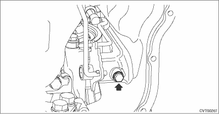
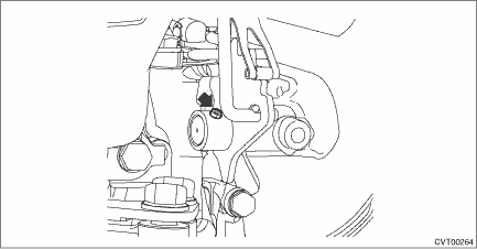
4. Install the parking rod to the manual plate. 5. Insert the parking rod into the transmission case, and install the shift connecting rod of the manual valve to the manual plate.
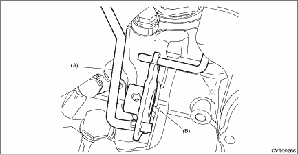
6. Insert the shifter arm shaft to the transmission assembly, install the manual plate to the shifter arm shaft, and secure the shifter arm shaft with a bolt. NOTE: Do not damage the lip of oil seal press-fitted in the case. Tightening torque: 7 N·m (0.7 kgf-m, 5.2 ft-lb)
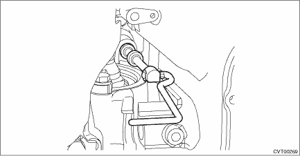
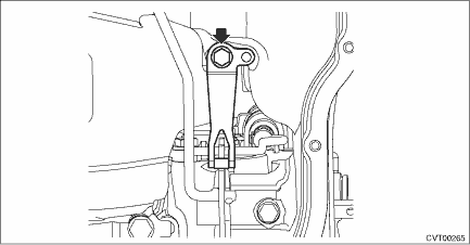
7. Install the detent spring. Tightening torque: 7 N·m (0.7 kgf-m, 5.2 ft-lb)
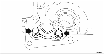
8. Install the spring pin. NOTE: Use new spring pin.
9. Install the inhibitor switch. Inhibitor Switch > INSTALLATION 10. Adjust the inhibitor switch. Inhibitor Switch > ADJUSTMENT 11. Install the oil strainer and oil pan. Oil Pan and Strainer > INSTALLATION 12. Install the transmission assembly. Automatic Transmission Assembly > INSTALLATION |
 Inspection
Make sure that the manual plate and detent spring are not worn or otherwise damaged. ...

Other materials:
Removal
1. REAR GATE PANEL1. Disconnect the ground terminal from battery sensor. NOTE2. Remove the rod - power rear gate. (Model with power rear gate) Power Rear Gate Rod > REMOVAL3. Remove the trim panel - rear gate. Rear Gate Trim > REMOVAL4. Remove the garnish assembly - rear gate. Rear Gate Garnish ...
