Subaru Legacy BN/BS (2015-2019) Service Manual: Installation
1. Clean the mating surface of valve cover and transmission side. 2. Check the control valve body for dust and other foreign matter. 3. Install the O-rings. NOTE: • Use new O-rings. • Apply CVTF to the O-rings.
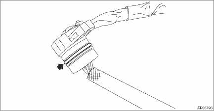
4. Install the transmission harness. Tightening torque: 7 N·m (0.7 kgf-m, 5.2 ft-lb)
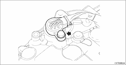
5. Attach the gasket. NOTE: Use a new gasket. 6. Apply liquid gasket to the oval hole of gasket. Liquid gasket: THREE BOND 1215B or equivalent
7. Connect the transmission harness connector to the control valve body, and install the valve cover. Tightening torque: 8 N·m (0.8 kgf-m, 5.9 ft-lb)
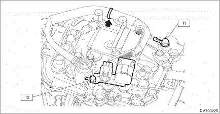
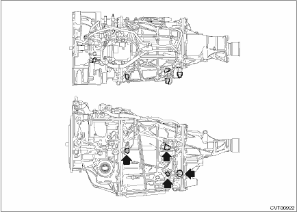
8. Install the transmission harness connector to the harness stay. 9. Install the transmission harness stay, transmission ground terminal and harness clip. Tightening torque: T1: 14 N·m (1.4 kgf-m, 10.3 ft-lb) T2: 7 N·m (0.7 kgf-m, 5.2 ft-lb)
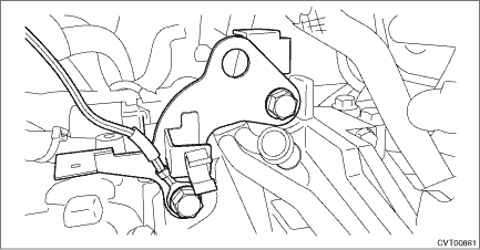
10. Connect the harness connector to the inhibitor switch. 11. Connect the harness connector to the turbine speed sensor, primary speed sensor, secondary speed sensor and secondary pressure sensor.
12. Install the transmission hanger and transmission radio ground cord. Tightening torque: 41 N·m (4.2 kgf-m, 30.2 ft-lb)
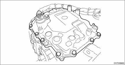
13. Install the air breather hose. Air Breather Hose > INSTALLATION 14. Install the transmission case cover (large). Tightening torque: 8 N·m (0.8 kgf-m, 5.9 ft-lb) 15. Install the transmission assembly. Automatic Transmission Assembly > INSTALLATION 16. Adjust the CVTF level. CVTF > ADJUSTMENT |

 Inspection
1. Visually check the harness and connector for damage or crack.2. Check the harness terminal for rust, disconnection or poor contact.3. Check the continuity between harness terminals.NOTE:For details ...

Other materials:
Inspection
• Check each component for scratches, damage or other faults.• Using the ST, check the backlash of pinion gear.ST1 498247001MAGNET BASEST2 498247100DIAL GAUGESpecification:0.13 — 0.18 mm (0.0051 — 0.0071 in)• Measure the hypoid gear backlash, and then adjust it to be with ...
