Subaru Legacy BN/BS (2015-2019) Service Manual: Installation
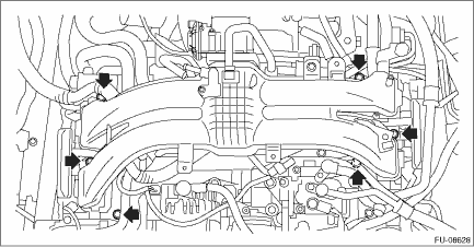
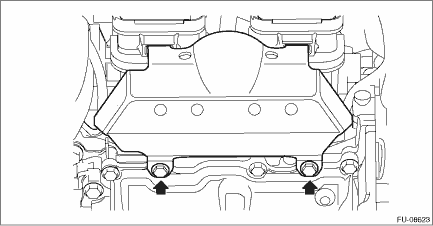
1. Install the intake manifold assembly onto cylinder head. NOTE: • Use a new gasket. • Be careful not to let the engine harness be caught by the parts. Tightening torque: 25 N·m (2.5 kgf-m, 18.4 ft-lb)
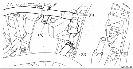
2. Connect the fuel delivery tube and evaporation hose. (1) Connect the evaporation hose (C) to the fuel pipe assembly. (2) Connect the connector of the fuel delivery tube (B) to the fuel pipe assembly, and secure the fuel delivery tube using clip (A). CAUTION: • Check that there is no damage or dust on the quick connector. If necessary, clean the seal surface of the pipe. • Make sure that the quick connector is securely connected.
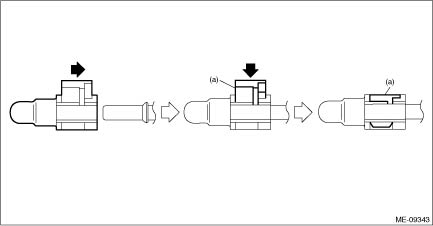
3. Connect the fuel delivery pipe to the fuel pipe LH. CAUTION: • Check that there is no damage or dust on the quick connector. If necessary, clean the seal surface of the pipe. • When connecting the quick connector, make sure to insert it all the way in before locking the slider. • When it is difficult to lock the slider, check that the connector is fully inserted. • After locking the slider, check again that the quick connector is securely connected. NOTE: Connect the quick connector as shown in the figure.
4. Connect the connector (A) to the tumble generator valve, and connect the connector (B) to the fuel injector #4.
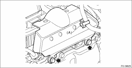
5. Install the intake manifold protector LH, and install the clip (A) securing the engine harness to the intake manifold protector LH. Tightening torque: 6.4 N·m (0.7 kgf-m, 4.7 ft-lb)
6. Install the clip (A) securing the engine harness to the intake manifold assembly, and connect the connector (B) to the tumble generator valve and connect the connector (C) to the fuel injector #3. 7. Connect the fuel delivery pipe to the fuel pipe RH. CAUTION: • Check that there is no damage or dust on the quick connector. If necessary, clean the seal surface of the pipe. • When connecting the quick connector, make sure to insert it all the way in before locking the slider. • When it is difficult to lock the slider, check that the connector is fully inserted. • After locking the slider, check again that the quick connector is securely connected. NOTE: Connect the quick connector as shown in the figure.
8. Install the intake manifold protector RH. Tightening torque: 6.4 N·m (0.7 kgf-m, 4.7 ft-lb)
9. Connect the connector to the EGR control valve.
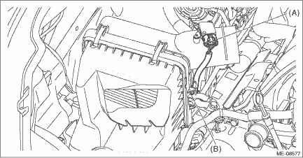
10. Install the air cleaner case (rear) together with the air cleaner element. Air Cleaner Case > INSTALLATION 11. Secure the bulkhead wiring harness with clip (B) and connect the connector (A) to the mass air flow and intake air temperature sensor.
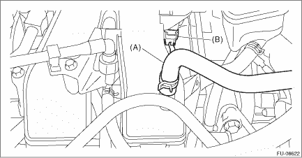
12. Install the air intake duct. Air Intake Duct > INSTALLATION 13. Connect the brake booster vacuum hose (A) and the connector (B) of the purge control solenoid valve.
14. Tighten the bolt securing the EGR cooler to the EGR control valve. NOTE: Use a new gasket. Tightening torque: T1: 9 N·m (0.9 kgf-m, 6.6 ft-lb) 15. Tighten the bolts holding the EGR cooler to the cylinder head RH. Tightening torque: T2: 6.4 N·m (0.7 kgf-m, 4.7 ft-lb)
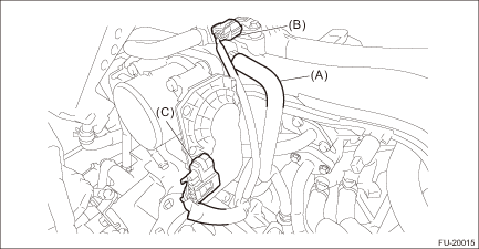
16. Connect the PCV hose (A) to intake manifold assembly. 17. Connect the connector (B) to the manifold absolute pressure sensor. 18. Connect the connector (C) to throttle body.
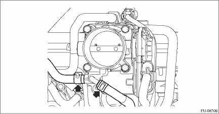
19. Connect the preheater hoses to the throttle body.
20. Install the air intake boot. Air Intake Boot > INSTALLATION 21. Connect the ground terminal to battery sensor. NOTE 22. Fill engine coolant. Engine Coolant > REPLACEMENT |


 Assembly
1. Install the fuel pipe assembly to the intake manifold assembly.Tightening torque:6.4 N·m (0.7 kgf-m, 4.7 ft-lb)2. Install the fuel delivery pipe to the intake manifold assembly.CAUTION:&bull ...
 Inspection
1. Check that the intake manifold assembly and fuel pipe assembly have no deformation, cracks and other damages.2. Check that the hose has no cracks, damage or loose part.3. Check tumble generator val ...
Other materials:
Inspection
1. INSPECTION WITHOUT USING CAN DIAGNOSTICBefore performing diagnosis, check the following items that might affect troubles of each module.1. Check the battery. Battery > INSPECTION Battery > INSPECTION2. Check the fuse condition.Make sure that ampere of the fuse is setting value, and it is not bl ...
