Subaru Legacy BN/BS (2015-2019) Service Manual: Installation
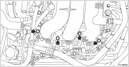
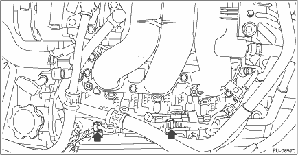
1. Install the intake manifold onto cylinder heads. NOTE: Use a new gasket. Tightening torque: 25 N·m (2.5 kgf-m, 18.4 ft-lb) • RH side
• LH side
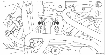
2. Install the bolts securing the EGR pipe B to the EGR control valve. NOTE: Use a new gasket. Tightening torque: 6.4 N·m (0.7 kgf-m, 4.7 ft-lb)
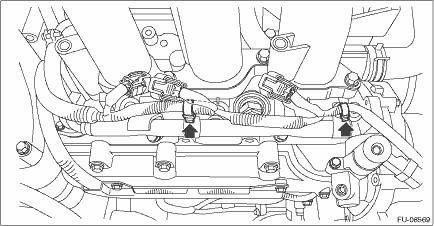
3. Install the clip securing the engine harness to the fuel injector pipe RH.
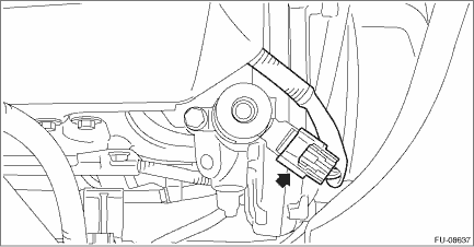
4. Connect the connector to the intake oil flow control solenoid valve RH.
5. Install the clip securing the engine harness to the fuel injector pipe LH.
6. Connect the connectors to the oil temperature sensor, engine coolant temperature sensor and intake oil flow control solenoid valve LH.
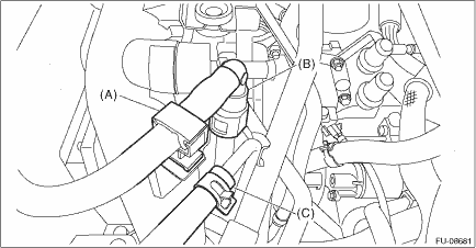
7. Connect the fuel delivery tube and evaporation hose. (1) Connect the evaporation hose (C) to the fuel pipe assembly. (2) Connect the quick connector of the fuel delivery tube (B) to the fuel pipe assembly, and secure the fuel delivery tube using clip (A). CAUTION: • Check that there is no damage or dust on the quick connector. If necessary, clean the seal surface of the pipe. • Make sure that the quick connector is securely connected.
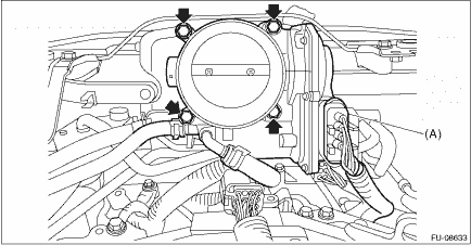
8. Install the throttle body to the intake manifold, and connect the connector (A) to the throttle body. NOTE: Use a new gasket. Tightening torque: 8 N·m (0.8 kgf-m, 5.9 ft-lb)
9. Connect the engine harness connector.
10. Install the fuel injector. Fuel Injector > INSTALLATION 11. Install the air intake boot. Air Intake Boot > INSTALLATION 12. Connect the brake booster vacuum hose.
13. Connect the ground terminal to battery sensor. NOTE 14. Install the collector cover. |


 Assembly
NOTE:When assembling the nipple, apply liquid gasket.Liquid gasket:THREE BOND 1105 (Part No. 004403010) or equivalentTightening torque:17 N·m (1.7 kgf-m, 12.5 ft-lb)1. Install the purge control ...
 Inspection
1. Check that the intake manifold and fuel pipe assembly have no deformation, cracks and other damages.2. Check that the hose has no cracks, damage or loose part. ...
Other materials:
Dtc b1804 short in driver's airbag
DIAGNOSIS START CONDITION:Ignition voltage is 10 V to 16 V.DTC DETECTING CONDITION:Short circuit between driver’s airbag circuit and other circuitCAUTION:Before performing diagnosis, refer to “CAUTION” in “General Description”. General Description > CAUTIONNOTE:Prior t ...
