Subaru Legacy BN/BS (2015-2019) Service Manual: Installation
1. Wipe off grease, oil and dust on the mating surfaces of transmission cases with cleaning solvent. 2. Install the shifter fork and rod. Shifter Fork and Rod > INSTALLATION 3. Install the reverse idler gear. Reverse Idler Gear > INSTALLATION 4. Select the drive pinion shim. Drive Pinion Shaft Assembly > INSTALLATION 5. Install the taper roller bearing outer race to the transmission case LH side, and install the differential side retainer with the O-ring removed. 6. Install the front differential assembly. 7. Install the main shaft assembly. NOTE: Align to install the needle bearing knock pin hole to the transmission case knock pin. 8. Install the selected drive pinion shims and drive pinion shaft assembly. NOTE: Install the transmission case knock pin into the roller bearing knock pin hole. 9. Tighten the left and right side of the transmission case with the17 mounting bolts. NOTE: • Insert bolts (11) and (16) from the LH side of the transmission case. • Match the cases together so that the drive pinion shims are not caught between the cases. Tightening torque: 8 mm bolt 25 N·m (2.5 kgf-m, 18.4 ft-lb)
40 N·m (4.1 kgf-m, 29.5 ft-lb)
10. Install the taper roller bearing outer race to the RH side of the transmission case. 11. Tighten the bearing mounting bolts. Tightening torque: 30 N·m (3.1 kgf-m, 22.1 ft-lb)
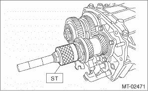
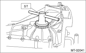
12. Perform backlash adjustment of the hypoid driven gear and preload adjustment of the taper roller bearing. (1) Attach the ST on drive pinion shaft assembly.
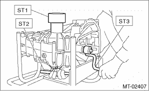
(2) Place the transmission case with the LH side facing downward, and put ST1 on the taper roller bearing outer race. (3) Screw in the differential side retainer from the bottom into left case using ST2. Fit the ST3 on the main shaft of the transmission. Shift the gear into 4th or 5th, and turn the shaft several times. Screw in the differential side retainer while rotating the ST3 until a slight resistance is felt on ST2. This is the contact point of the hypoid driven gear and the drive pinion shaft. Repeat the above sequence several times to ensure the contact point.
(4) Remove the WEIGHT, and screw in the differential side retainer without the O-ring into the RH side of the transmission case, and stop at the point where a slight resistance is felt. NOTE: In this condition, the backlash between hypoid driven gear and drive pinion shaft is zero.
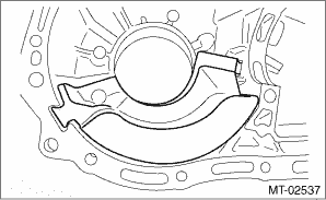
(5) Loosen the differential side retainer on the LH side of the transmission case by 3 notches, and turn the differential side retainer on the RH side of the transmission case by 3 notches in order to apply backlash. (6) Screw in the differential side retainer of the RH side of the transmission case additionally by 1 notch in order to apply preload on taper roller bearing. (7) Tighten temporarily both the retainer lock plates LH and RH, and put marks on both the differential side retainer and retainer lock plate for later readjustment. NOTE: When it is difficult to attach the retainer lock plate, turn over the retainer lock plate and attach. (8) Turn the transmission main shaft several times while tapping around the differential side retainer lightly with a plastic hammer. 13. Inspect and adjust backlash and tooth contact of the hypoid driven gear. Front Differential Assembly > INSPECTION 14. Separate the transmission case into left and right parts. Transmission Case > REMOVAL 15. Check each shifter fork. Shifter Fork and Rod > INSPECTION 16. Select a main shaft rear plate. Main Shaft Assembly > ADJUSTMENT 17. Install the front oil guide. NOTE: Fit in all the way.
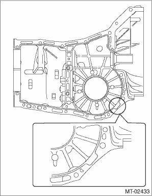
18. Apply liquid gasket, then join the right side and left side of the case together. Liquid gasket: THREE BOND 1215B or equivalent
19. Tighten 17 bolts with brackets and clips as shown in the figure. NOTE: • Insert bolts (11) and (16) from the LH side of the transmission case. • Match the cases together so that the drive pinion shims are not caught between the cases. Tightening torque: 8 mm bolt 25 N·m (2.5 kgf-m, 18.4 ft-lb)
40 N·m (4.1 kgf-m, 29.5 ft-lb)
20. Tighten the bearing mounting bolts. Tightening torque: 30 N·m (3.1 kgf-m, 22.1 ft-lb)
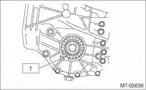
21. Remove the retainer lock plate, and loosen the differential side retainer until the groove of the O-ring appears. Fit the O-ring into the groove and tighten the differential side retainer into the position where it was not loosened. NOTE: • When loosening the differential side retainer, record the number of the turns made. • Perform this for both left and right differential side retainers. • Use new O-rings. • Apply transmission gear oil to O-ring. 22. Install the retainer lock plate. Tightening torque: T: 25 N·m (2.5 kgf-m, 18.4 ft-lb)
23. Install the transfer case together with the extension case assembly. Transfer Case and Extension Case Assembly > INSTALLATION 24. Install the clutch release lever and release bearing. Release Bearing and Lever > INSTALLATION 25. Install the manual transmission assembly to the vehicle. Manual Transmission Assembly > INSTALLATION |
 10 mm bolt
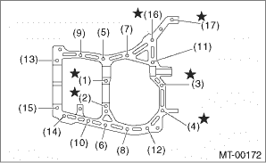
 Inspection
Check the transmission case for cracks, damage, or oil leaks. ...

Other materials:
Preparation tool
CAUTION:To measure the voltage and resistance of airbag system component, be sure to use the specified test harness.1. SPECIAL TOOL• SUBARU SELECT MONITORILLUSTRATIONTOOL NUMBERDESCRIPTIONREMARKS — (Newly adopted tool)SUBARU SELECT MONITOR 4Used for setting of each function and troubleshooti ...
