Subaru Legacy BN/BS (2015-2019) Service Manual: Installation
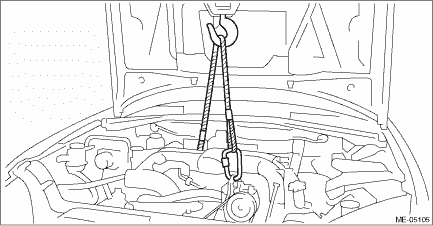
1. Position the engine in engine compartment and align it with transmission. NOTE: Be careful not to damage adjacent parts or body panels with crank pulley, oil level gauge, etc.
2. Install the bolts which hold upper side of transmission to engine. Tightening torque: 50 N·m (5.1 kgf-m, 36.9 ft-lb)
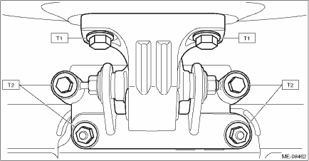
3. Place the front cushion rubber together with the front mounting bracket to the cradle, and install the front cushion rubber to the engine mounting bracket to install the front mounting bracket to the cradle and the bracket. Tightening torque: T1: 25 N·m (2.5 kgf-m, 18.4 ft-lb) T2: 60 N·m (6.1 kgf-m, 44.3 ft-lb)
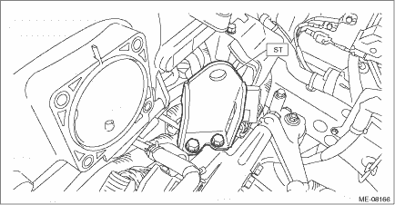
4. Remove the lifting device and wire ropes. 5. Remove the ST.
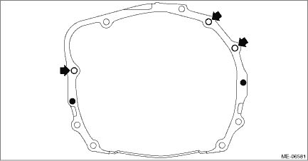
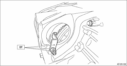
6. Install the torque converter clutch to drive plate. (1) Remove the ST from torque converter clutch case. NOTE: Be careful not to drop the ST into the torque converter clutch case when removing the ST.
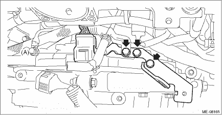
(2) Insert the wrench into the crank pulley bolt, and rotate the crank pulley to attach the four bolts securing the torque converter clutch to the drive plate. NOTE: Be careful not to drop bolts into the torque converter clutch case. Tightening torque: 25 N·m (2.5 kgf-m, 18.4 ft-lb) (3) Fit the plug to service hole.
7. Install the starter. Starter > INSTALLATION 8. Lift up the vehicle. 9. Install the bolts and nuts which hold lower side of the transmission to engine. Tightening torque: 50 N·m (5.1 kgf-m, 36.9 ft-lb)
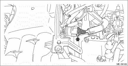
10. Connect the ground cable. Tightening torque: 7.5 N·m (0.8 kgf-m, 5.5 ft-lb)
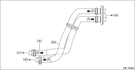
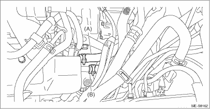
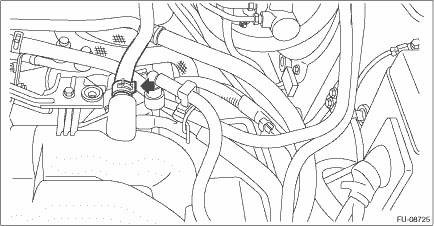
11. Install the front exhaust pipe. Front Exhaust Pipe > INSTALLATION 12. Lower the vehicle. 13. Connect the fuel delivery tube and evaporation hose. (1) Connect the evaporation hose (C) to the fuel pipe assembly. (2) Connect the quick connector of the fuel delivery tube (B) to the fuel pipe assembly, and secure the fuel delivery tube using clip (A). CAUTION: • Check that there is no damage or dust on the quick connector. If necessary, clean the seal surface of the pipe. • Make sure that the quick connector is securely connected.
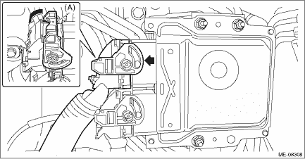
14. Move the lock lever (A) in the direction of arrow, and connect the engine harness connector to ECM.
15. Connect the engine harness connector.
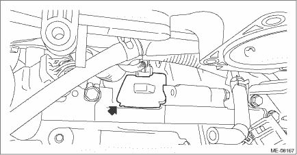
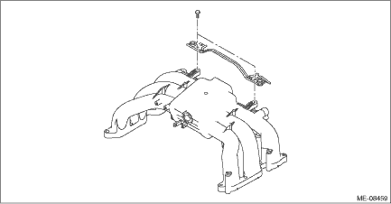
16. Install the collector cover bracket to the intake manifold. Tightening torque: 6.5 N·m (0.7 kgf-m, 4.8 ft-lb)
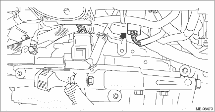
17. Install the engine hanger bracket, and install the engine harness connector (A) to the engine hanger bracket. Tightening torque: 19 N·m (1.9 kgf-m, 14.0 ft-lb)
18. Connect the sensor harness connector.
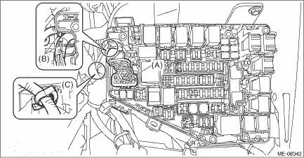
19. Install the throttle body. Throttle Body > INSTALLATION 20. Place the engine harness and attach the engine harness to the clip (C). 21. Attach the engine harness to the claw (B) of the main fuse box and connect the engine harness connector (A) to the main fuse box.
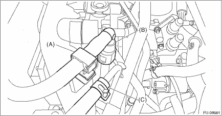
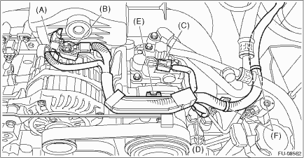
22. Connect the heater inlet hose (A) and the heater outlet hose (B). NOTE: Be careful not to mix up the heater inlet hose and the heater outlet hose when connecting them.
23. Connect the brake booster vacuum hose.
24. Connect the A/C pressure hose to A/C compressor. Hose and Pipe > INSTALLATION 25. Set the generator cord, and secure the fuel pipe protector (LH) using clip (F). 26. Install the harness cover (E) to the collector cover bracket. 27. Connect the connector (C) and connector (D) to the A/C compressor. 28. Connect the connector (A) and terminal (B) to the generator. Tightening torque: 15 N·m (1.5 kgf-m, 11.1 ft-lb)
29. Install the radiator. Radiator > INSTALLATION 30. Install the air cleaner case (rear) together with the air cleaner element. Air Cleaner Case > INSTALLATION 31. Install the air intake boot. Air Intake Boot > INSTALLATION 32. Install the air intake duct. Air Intake Duct > INSTALLATION 33. Connect the ground terminal to battery sensor. NOTE 34. Fill engine coolant. Engine Coolant > REPLACEMENT 35. Charge the A/C system with refrigerant. Refrigerant Charging Procedure > PROCEDURE 36. Check the CVTF level and replenish it if necessary. CVTF > INSPECTION 37. Install the collector cover. 38. Set the front hood to the normal position. NOTE 39. Close the front hood. |
 Inspection
1. Check that the pipes, hoses, connectors and clips are securely connected.2. Check the engine coolant is at specified level.3. Check CVTF is at the specified level.4. Start the engine and check for ...
 Engine mounting
...
Other materials:
Dtc b1693 door sensor rh initialization incomplete
DIAGNOSIS START CONDITION:Ignition voltage is 10 V to 16 V.DTC DETECTING CONDITION:Front door impact sensor RH unit malfunction (sensor type abnormal, sensor unit initialization error)CAUTION:Before performing diagnosis, refer to “CAUTION” in “General Description”. General D ...
