Subaru Legacy BN/BS (2015-2019) Service Manual: Intake manifold vacuum inspection
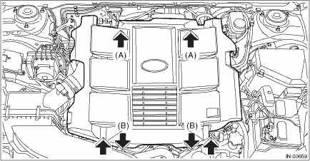
1. Warm up the engine. 2. Remove the collector cover. (1) Carefully pull up the rear of collector cover at two positions (A). (2) Carefully pull up the front of collector cover at two positions (B) while moving it forward.
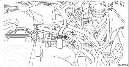
3. Disconnect the brake booster vacuum hose from the intake manifold, and attach the vacuum gauge.
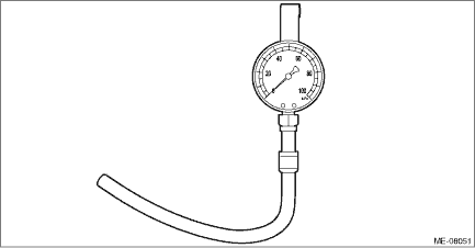
4. Keep the engine at idle speed and read the vacuum gauge indication. NOTE: Condition of engine inside can be diagnosed by observing the behavior of the vacuum gauge needle as described in table below. Intake manifold vacuum (at idling, A/C OFF): Standard Less than −60.0 kPa (−450 mmHg, −17.72 inHg)
5. After inspection, install the related parts in the reverse order of removal. | ||||||||||||||
 Intake and exhaust valve specification
Refer to “Cylinder Head” for removal and installation procedures of the intake and exhaust valves. Cylinder Head > REMOVAL Cylinder Head > INSTALLATION ...
 Piston specification
Refer to “Cylinder Block” for removal and installation procedures of pistons. Cylinder Block > REMOVAL Cylinder Block > INSTALLATION ...
Other materials:
Installation
1. Apply engine oil to camshaft journals, and install the camshaft.2. Install the camshaft cap.(1) Apply liquid gasket sparingly to back side of the front camshaft cap as shown in the figure.NOTE:• Install within 5 min. after applying liquid gasket.• Do not apply liquid gasket excessivel ...
