Subaru Legacy BN/BS (2015-2019) Service Manual: Removal
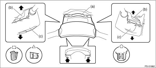
CAUTION: • If the steering wheel and steering angle sensor are removed, perform “VSC(VDC) Centering Mode” of the VDC. VDC Control Module and Hydraulic Control Unit (VDCCM&H/U) > ADJUSTMENT • Before handling the airbag system components, always refer to “CAUTION” of “General Description” in “AIRBAG SYSTEM”. General Description > CAUTION • Always use the steering wheel puller for removal to avoid deforming the steering wheel. • If the steering wheel has been removed, make sure that the steering roll connector is not turned from the original position. 1. Position the front wheels straight ahead. 2. Disconnect the ground terminal from the battery sensor, and wait for at least 60 seconds before starting work. NOTE 3. Remove the driver’s airbag module. Driver’s Airbag Module > REMOVAL 4. Remove the steering wheel. Steering Wheel > REMOVAL 5. Remove the cover assembly - column. (1) Remove the clips, and remove the cover - column (a). (2) Remove the screws. (3) Release the claws, and remove the cover assembly - column UPR (b) and the cover assembly - column LWR (c).
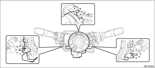
6. Remove the steering roll connector. CAUTION: Make sure that the steering roll connector is not turned from the original position. (1) Disconnect the connector under the steering roll connector. (2) Release the claws and remove the steering roll connector.
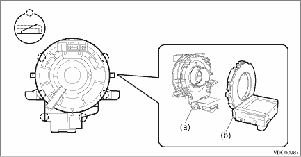
7. Remove the steering angle sensor. (1) Release the claws and remove the steering angle sensor (b) from the steering roll connector (a).
|

 Installation
CAUTION:• When removing, installing or replacing the VDCCM&H/U, VDCCM&H/U bracket, steering wheel or steering angle sensor (steering roll connector), perform “VSC(VDC) Centering Mode&rdquo ...
Other materials:
List
ItemContent / display rangeTrip CountTime stamp information General Description > CAUTIONCountTime CountBATT voltageImmobilizer CM battery voltageIgnition SW inputIgnition switch statuskey-lock warning SW InputKey warning switch statusImmobilizer indicator outputSecurity indicator output statusImmob ...
