Subaru Legacy BN/BS (2015-2019) Service Manual: Installation
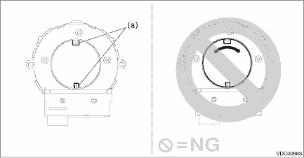
CAUTION: • When removing, installing or replacing the VDCCM&H/U, VDCCM&H/U bracket, steering wheel or steering angle sensor (steering roll connector), perform “VSC(VDC) Centering Mode” of the VDC. VDC Control Module and Hydraulic Control Unit (VDCCM&H/U) > ADJUSTMENT • Before handling the airbag system components, always refer to “CAUTION” of “General Description” in “AIRBAG SYSTEM”. General Description > CAUTION 1. Install the steering angle sensor. (1) Apply grease to the protrusion (a) of the new steering angle sensor. CAUTION: Do not rotate the steering angle sensor protrusion.
(2) Align the center of steering roll connector. Roll Connector > INSTALLATION (3) Align the position of the protrusion and install the steering angle sensor to the steering roll connector. 2. Install the cover assembly - column. 3. Install the steering wheel. Tightening torque: Steering wheel: 39 N·m (4.0 kgf-m, 28.8 ft-lb) Clearance: Between cover assembly - column and steering wheel: 4 — 6 mm (0.16 — 0.24 in) 4. Install the driver’s airbag module. Driver’s Airbag Module > INSTALLATION 5. Connect the ground terminal to battery sensor. NOTE 6. Perform the neutral position setting of the steering angle sensor. VDC Control Module and Hydraulic Control Unit (VDCCM&H/U) > ADJUSTMENT |
 Removal
CAUTION:• If the steering wheel and steering angle sensor are removed, perform “VSC(VDC) Centering Mode” of the VDC. VDC Control Module and Hydraulic Control Unit (VDCCM&H/U) > ADJU ...

Other materials:
Removal
1. Disconnect the ground terminal from battery sensor. NOTE2. Remove the air intake duct. Air Intake Duct > REMOVAL3. Remove the clip (A), and loosen the clamps (B) and (C).4. Remove the air intake boot from the throttle body, and move it to the left side wheel apron.5. Disconnect the transmission ...
