Honda Civic manuals

Subaru Legacy BN/BS (2015-2019) Service Manual: Dtc p2138 throttle/pedal position sensor/switch "d"/"e" voltage correlation

Subaru Legacy BN/BS (2015-2019) Service Manual / Engine (diagnostics)(h4do) / Diagnostic procedure with diagnostic trouble code (dtc) / Dtc p2138 throttle/pedal position sensor/switch "d"/"e" voltage correlation

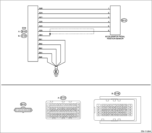
DTC DETECTING CONDITION:

Immediately at fault recognition

TROUBLE SYMPTOM:

Improper idling

Poor driving performance

CAUTION:

After servicing or replacing faulty parts, perform Clear Memory Mode Clear Memory Mode > OPERATION, and Inspection Mode Inspection Mode > PROCEDURE.

WIRING DIAGRAM:

Engine Electrical System ENGINE TYPE FB (WITHOUT PUSH BUTTON START) Engine Electrical System > WIRING DIAGRAM

Engine Electrical System ENGINE TYPE FB (WITH PUSH BUTTON START) Engine Electrical System > WIRING DIAGRAM

STEPCHECKYESNO

1.CHECK ACCELERATOR PEDAL POSITION SENSOR OUTPUT.

1) Turn the ignition switch to ON.

2) Measure the voltage between ECM connector and chassis ground.

Connector & terminal

Main accelerator pedal position sensor signal

(E134) No. 29 (+) — Chassis ground (−):

Sub accelerator pedal position sensor signal

(E134) No. 31 (+) — Chassis ground (−):

Is the difference in measured values for the main accelerator pedal position sensor signal and the sub accelerator pedal position sensor signal 0 V-

Diagnostic Procedure with Diagnostic Trouble Code (DTC) > DTC P2138 THROTTLE/PEDAL POSITION SENSOR/SWITCH "D"/"E" VOLTAGE CORRELATION

Diagnostic Procedure with Diagnostic Trouble Code (DTC) > DTC P2138 THROTTLE/PEDAL POSITION SENSOR/SWITCH "D"/"E" VOLTAGE CORRELATION

2.CHECK ACCELERATOR PEDAL POSITION SENSOR OUTPUT.

1) Measure the voltage between accelerator pedal position sensor connector and chassis ground.

Connector & terminal

(B315) No. 6 (+) — Chassis ground (−):

(B315) No. 3 (+) — Chassis ground (−):

Is the difference in measured values for the main accelerator pedal position sensor signal and the sub accelerator pedal position sensor signal 0 V-

Replace the accelerator pedal. Accelerator Pedal

Repair the harness and connector.

NOTE:

In this case, repair the following item:

Open circuit of harness between ECM connector and accelerator pedal position sensor connector

Short circuit to ground in harness between ECM connector and accelerator pedal position sensor connector

3.CHECK HARNESS BETWEEN ECM AND ACCELERATOR PEDAL POSITION SENSOR CONNECTOR.

Measure the resistance of harness between accelerator pedal position sensor connector and chassis ground.

Connector & terminal

(B315) No. 5 — Chassis ground:

(B315) No. 2 — Chassis ground:

Is the resistance less than 5 --

Repair the poor contact of ECM connector.

Repair the harness and connector.

NOTE:

In this case, repair the following item:

Open circuit of harness between ECM connector and accelerator pedal position sensor connector

Open circuit of harness between ECM connector and engine ground

Poor contact of ECM connector

Poor contact of joint connector

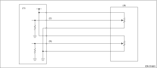
1. OUTLINE OF DIAGNOSIS

Judge as NG when the signal level of accelerator pedal position sensor 1 is different from the accelerator pedal position sensor 2.

2. COMPONENT DESCRIPTION

(1)

Engine control module (ECM)

(3)

Accelerator pedal position sensor 2 signal

(4)

Accelerator pedal position sensor

(2)

Accelerator pedal position sensor 1 signal

3. EXECUTION CONDITION

Secondary Parameters

Execution condition

Battery voltage

≥ 6 V

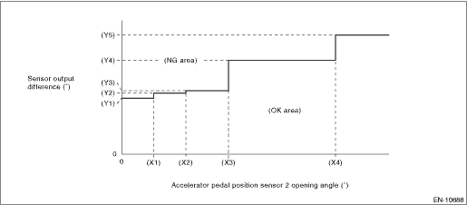
4. GENERAL DRIVING CYCLE

Always perform the diagnosis continuously.

5. DIAGNOSTIC METHOD

If the duration of time while the following conditions are met is longer than the time indicated, judge as NG.

Judgment Value

Malfunction Criteria

Threshold Value

Signal difference between two sensors

Within NG range of Details of Judgment value

Details of Judgment Value

(X1)

0.6 °

(X2)

1.2 °

(X3)

2 °

(X4)

4 °

(Y1)

1.465 °

(Y2)

1.597 °

(Y3)

1.663 °

(Y4)

2.455 °

(Y5)

3.116 °

Time Needed for Diagnosis: 116 ms

Malfunction Indicator Light Illumination: Illuminates as soon as a malfunction occurs.

Dtc p2195 a/f /o2 sensor signal biased/stuck lean bank 1 sensor 1
DTC DETECTING CONDITION:Detected when two consecutive driving cycles with fault occur.CAUTION:After servicing or replacing faulty parts, perform Clear Memory Mode Clear Memory Mode > OPERATION, and I ...

Dtc p2135 throttle/pedal position sensor/switch "a"/"b" voltage correlation
DTC DETECTING CONDITION:Immediately at fault recognitionTROUBLE SYMPTOM:• Improper idling• Poor driving performanceCAUTION:After servicing or replacing faulty parts, perform Clear Memory M ...

Other materials:

Electrical specification
• Body integrated unitFor I/O signals of the body integrated unit, refer to BODY CONTROL SYSTEM (DIAGNOSTICS). Control Module I/O Signal• Engine CMFor I/O signals of ECM, refer to ENGINE (DIAGNOSTICS). Engine Control Module (ECM) I/O Signal Engine Control Module (ECM) I/O Signal• ...

© 2017-2024 Copyright www.sulegacy.com