
Subaru Legacy BN/BS (2015-2019) Service Manual: Inspection
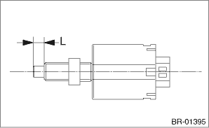
1. INSPECT THE SPECIFIED POSITION 1. Measure the specified position of the stop light switch ends. Specified position L: 3.6 mm ±0.4 mm (0.14 in ±0.016 in)
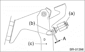
2. Measure the clearance between the end of the stop light switch and the stopper. CAUTION: Be careful not to rotate the stop light switch. Stop light switch clearance A: 1.1 mm (0.03 — 0.04 in)
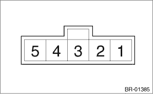
3. Adjust the position of the stop light switch if the inspection result is not within the standard value. Stop Light Switch > ADJUSTMENT 4. If the stop light switch does not operate properly or it is not secured at the specified position after adjustment, replace with a new part. 2. INSPECT THE RESISTANCE 1. Check the resistance between connector terminals. Preparation tool: Circuit tester
2. Replace the stop light switch if the inspection result is not within the standard value. |
 Installation
1. Install the stop light switch onto the bracket with screws and position it with the nut.2. Adjust the stop light switch position, and then tighten the nut. Stop Light Switch > ADJUSTMENTTightening ...
 Clutch system
...
Other materials:
Disassembly
1. Remove the front reduction driven shaft from the front reduction driven gear.2. Remove the snap ring.3. Remove the retaining plate, drive plate, driven plate and dish plate.4. Remove the seal ring from front reduction driven shaft.5. Remove the ball bearing, while tapping the entire circumference ...
