Subaru Legacy BN/BS (2015-2019) Service Manual: Inspection
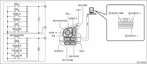
1. SATELLITE SWITCH ASSEMBLY 1. Measure the resistance between connector terminals. Preparation tool: Circuit tester
2. Apply battery voltage between the connector terminals to check lighting condition of illumination inside the switch.
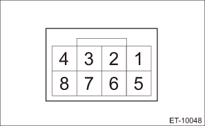
3. If the result of the measurement is not at the standard, replace the satellite switch assembly. 2. TELEMATICS BUTTON 1. Check the button. (1) Measure the resistance between connector terminals. Preparation tool: Circuit tester
• SOS button
• i-button
(2) Apply battery voltage between the connector terminals to check lighting condition of illumination inside the switch.
2. Check the indicator. (1) Check the continuity between the connectors.
3. Replace the overhead console or stereo camera cover assembly if the inspection result is not within the standard value. | ||||||||||||||||||||||||||||||||||||||||||||||||||||||||||||||||||||||||||||||||||
 )
) )
)
 Removal
1. SATELLITE SWITCH ASSEMBLYCAUTION:Before handling the airbag system components, refer to “CAUTION” of “General Description” in “AIRBAG SYSTEM”. General Descripti ...
 Installation
1. SATELLITE SWITCH ASSEMBLYCAUTION:• Before handling the airbag system components, refer to “CAUTION” of “General Description” in “AIRBAG SYSTEM”. General D ...
Other materials:
Removal
1. Disconnect the ground terminal from battery sensor. NOTE2. Remove the arm assembly - windshield wiper. Front Wiper Arm > REMOVAL3. Remove the cowl panel - side and the cowl panel assembly. Cowl Panel > REMOVALCAUTION:Before removing the cowl panel, use an air blower and nylon brush to sweep gr ...
