Subaru Legacy BN/BS (2015-2019) Service Manual: Inspection
1. MID SWITCH 1. Measure the resistance between connector terminals. Preparation tool: Circuit tester
2. Apply battery voltage between the connector terminals to check lighting condition of illumination inside the switch.
3. Replace the MID switch if the inspection result is not within the standard value. 2. TRIP RESET SWITCH 1. Measure the resistance between connector terminals. Preparation tool: Circuit tester
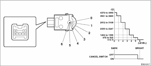
2. Replace the switch assembly - trip reset if the inspection result is not within the standard. 3. ILLUMINATION CONTROL SWITCH 1. Measure the resistance between connector terminals. Preparation tool: Circuit tester
2. Apply battery voltage between the connector terminals to check lighting condition of illumination inside the switch.
3. Replace the illumination control switch if the inspection result is not within the standard value. | |||||||||||||||||||||||||||||||||||||||||||||||||||||

 (UP)
(UP) (DOWN)
 Removal
1. MID SWITCHCAUTION:Before handling the airbag system components, refer to “CAUTION” of “General Description” in “AIRBAG SYSTEM”. General Description > CAUTION1. ...
 Installation
1. MID SWITCHCAUTION:• Before handling the airbag system components, refer to “CAUTION” of “General Description” in “AIRBAG SYSTEM”. General Description > CA ...
Other materials:
Removal
CAUTION:The hood COMPL - front is heavy. When removing and installing it, always work in a team of two or more persons.1. Open the hood COMPL - front.2. Remove the stay assembly - front hood.CAUTION:Do not remove the stop ring completely. Raise it to the position enough to remove the ball stud.(1) G ...
