Subaru Legacy BN/BS (2015-2019) Service Manual: Removal
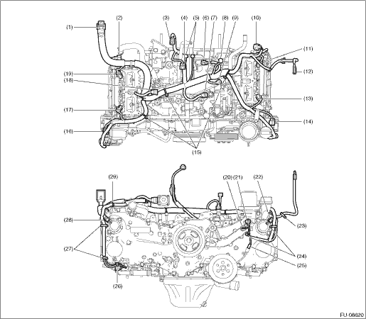
1. Disconnect the ground terminal from battery sensor. NOTE 2. Remove the intake manifold assembly. Intake Manifold Assembly > REMOVAL 3. Disconnect each connector to remove the engine wiring harness. • Structural diagram 1
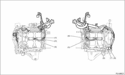
• Structural diagram 2
| |||||||||||||||||||||||||||||||||||||||||||||||||||||||||||||||||||||||||||||||||||||||||||||||||||||||||||||||

 Inspection
Check that the engine wiring harness does not have deformation, cracks and any other damage. ...
Other materials:
Removal
1. Remove the transmission assembly from the vehicle. Manual Transmission Assembly > REMOVAL2. Remove the two clips from the release lever and remove the release bearing.CAUTION:Be careful not to deform the clips.3. Remove the dust cover.(A)Release lever(B)Dust cover4. Remove the attachment point o ...
