Subaru Legacy BN/BS (2015-2019) Service Manual: Removal
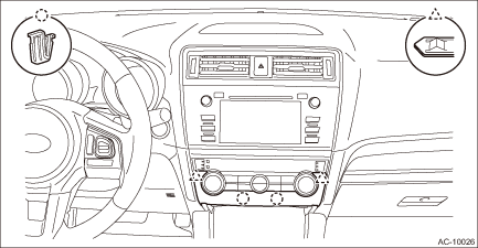
1. Disconnect the ground terminal from battery sensor. NOTE 2. Remove the heater control assembly. (1) Release the clips and claws, then detach the control module cover.
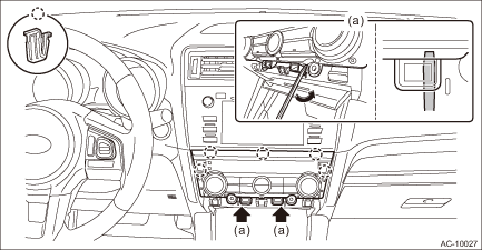
(2) Release the screws and clips, then detach the heater control assembly. CAUTION: • Insert a flat tip screwdriver wrapped with a protection tape into the position (a) shown in the figure, and move it in the arrow direction to remove the clip. When both clips are removed, pull out the heater control assembly by hand inserted through the space. • Be careful not to damage the clips and the control panel.
|
 Control panel
...
 Inspection
1. Check the illumination operation when battery voltage is applied between the connector terminals.Terminal No.Inspection conditionsSpecification2 (+) — 6 (−)Apply battery voltage.Light ON2. ...
Other materials:
Preparation tool
1. SPECIAL TOOLILLUSTRATIONTOOL NUMBERDESCRIPTIONREMARKS41099AJ130ST H4 (FA, FB)Used for holding and balancing the engine unit.99099AJ000ENGINE HANGER• Used for removing and installing transmission assembly.• Used together with CHAIN BALANCER (99099AJ010).99099AJ010CHAIN BALANCER• ...
