
Subaru Legacy BN/BS (2015-2019) Service Manual: Removal
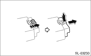
1. Disconnect the ground terminal from the battery sensor, and wait for at least 60 seconds before starting work. NOTE 2. Remove the rod - power rear gate. Power Rear Gate Rod > REMOVAL 3. Remove the trim panel - rear apron LH and trim panel - rear quarter trim UPR rear LH. Rear Quarter Trim > REMOVAL 4. Remove the power rear gate drive unit (PRG D/U). (1) Remove the harness clip, and disconnect the connector. NOTE: Pull the slide lock in the arrowed direction, and disconnect the PRG CM connector by pressing in the lock.
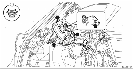
(2) Remove the bolts, and then remove the power rear gate drive unit (PRG D/U).
|

 Installation
1. Install the power rear gate drive unit (PRG D/U).Tightening torque:25 N·m (2.5 kgf-m, 18.4 ft-lb)2. Install the trim panel - rear apron LH and trim panel - rear quarter trim UPR rear LH.3. I ...
Other materials:
Dtc p0030 a/f / o2 heater control circuit bank 1 sensor 1
DTC DETECTING CONDITION:Detected when two consecutive driving cycles with fault occur.CAUTION:After servicing or replacing faulty parts, perform Clear Memory Mode Clear Memory Mode > OPERATION, and Inspection Mode Inspection Mode > PROCEDURE.WIRING DIAGRAM:• Engine Electrical System ENGINE T ...
