
Subaru Legacy BN/BS (2015-2019) Service Manual: Adjustment
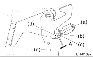
1. Loosen the lock nut, and adjust the stop light switch position until the clearance (A) between the threaded end of the stop light switch and stopper becomes 1.1 mm (0.04 in). Then, tighten the lock nut. Tightening torque: 8 N·m (0.8 kgf-m, 5.9 ft-lb) 2. Tighten the lock nut.
|
 Removal
1. Disconnect the ground terminal from the battery sensor, and wait for at least 60 seconds before starting work. NOTE2. Remove the cover assembly - instrument panel LWR driver. Instrument Panel Low ...
 Installation
1. Install the stop light switch onto the bracket with screws and position it with the nut.2. Adjust the stop light switch position, and then tighten the nut. Stop Light Switch > ADJUSTMENTTightening ...
Other materials:
Turn signal lever
To activate the right turn signal, push the
turn signal lever up. To activate the left
turn signal, push the turn signal lever
down. When the turn is finished, the lever
will return automatically. If the lever does
not return after cornering, return the lever
to the neutral position by han ...
© 2017-2026 Copyright www.sulegacy.com
