Subaru Legacy BN/BS (2015-2019) Service Manual: Adjustment
1. Install the transfer clutch assembly to the extension case with the transfer driven gear shims and thrust bearings removed.
2. Install the thrust bearing. NOTE: Make sure to install in the right direction.
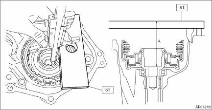
3. Using the ST, measure the height “A” from the ST end face to the thrust bearing catch surface of the transfer clutch assembly.
4. Using the ST, measure the height “B” from the transmission case mating surface to the end of ST.
5. Obtain the thickness of transfer driven gear shim using the following formula to select one to three transfer driven gear shims. T (mm) = A − B − (0.05 — 0.25) [T (in) = A − B − (0.002 — 0.01)] T: Transfer driven gear shim thickness A: Height from the ST end face to the transfer clutch assembly thrust bearing catch surface B: Height from the mating surface of the transmission case to the end of the ST 0.05 — 0.25 mm (0.002 — 0.01 in): Clearance
| ||||||||||||||


 Removal
1. Remove the transmission assembly. Automatic Transmission Assembly > REMOVAL2. Remove the extension case. Extension Case > REMOVAL3. Remove the transfer clutch assembly.4. Remove the thrust bearin ...
 Installation
1. Install the thrust bearing.NOTE:Make sure to install in the right direction.2. Install the transfer clutch assembly.3. Select the transfer driven gear shim. Transfer Clutch > ADJUSTMENT4. Attach t ...
Other materials:
Dtc b2781 steering lock cm control circuit
DTC DETECTING CONDITION:• When malfunction is detected in lock/unlock position detection sensor.• When the open or short circuit in the steering lock motor drive circuit is detected.TROUBLE SYMPTOM:• The steering lock cannot be released.• Engine will not start.CAUTION:For rep ...
