
Subaru Legacy BN/BS (2015-2019) Service Manual: Inspection
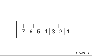
1. ACTUATOR LINK 1. Visually check the operating range of the link, and remove the foreign matter if any. 2. Operate the temperature control switch, and check that the link operates normally. 3. If it does not operate normally as the result of inspection, perform a unit inspection of motor - actuator mix. 2. CHECK ACTUATOR OPERATION 1. Check the actuator operation when battery voltage is applied between the connector terminals. CAUTION: Disconnect the battery immediately after the actuator stops operation. Otherwise, the motor may be damaged.
2. Measure the resistance between connector terminals. Preparation tool: Circuit tester
3. Connect the connector, turn the ignition switch to ON, and check the voltage between actuator terminals. • Driver’s seat
• Passenger’s seat
4. Replace the motor - actuator mix if it is found defective as a result of inspection. |
 Removal
1. DRIVER’S SIDE1. Disconnect the ground terminal from battery sensor. NOTE2. Remove the cover assembly - instrument panel LWR driver. Instrument Panel Lower Cover > REMOVAL3. Remove the bolts ...
 Installation
1. DRIVER’S SIDE1. When replacing the actuator with a new part, apply a thin coat of grease evenly to the side face (a) of lever pin by using approx. 5 mm (0.2 in) width and approx. 0.1 g (0.004 ...
Other materials:
Disassembly
1. Remove the drive pinion assembly.2. Flatten the tab of the lock nut.3. Using ST1 and ST2, fix at the spline portion of drive pinion shaft to remove the lock nut.ST1 18621AA000WRENCHST2 18667AA010HOLDER4. Remove the taper roller bearing and outer race from drive pinion shaft.5. Remove the in ...
