
Subaru Legacy BN/BS (2015-2019) Service Manual: Inspection
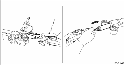
1. UNIT INSPECTION Check components for wear, damage or other faults. Adjust or replace if necessary. 2. LIMIT Make a measurements as follows. If it exceeds the specified service limits, adjust or replace. NOTE: When fixing the steering gearbox assembly in a vise, apply a wooden piece on the flange portion. Rack shaft sliding resistance: Limit: 360 N (37 kgf, 81 lbf) or less Left/right differential of sliding resistance: 20% or less
3. RACK SHAFT PLAY IN THE RADIAL DIRECTION Right-turn steering: Service limit: Direction Left-turn steering: Service limit: Direction Condition: L: 5 mm (0.20 in) P: 98 N (10 kgf, 22 lbf)
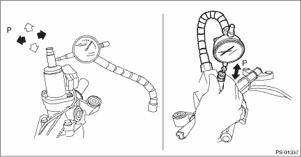
4. INPUT SHAFT PLAY In radial direction: Wear limit: 0.18 mm (0.0071 in) or less Condition: P = 98 N (10 kgf, 22 lbf) In axial direction: Wear limit: 0.27 mm (0.0106 in) or less Condition: P = 20 — 49 N (2 — 5 kgf, 4 — 11 lbf)
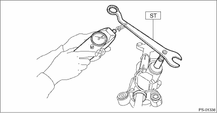
5. ROTATIONAL RESISTANCE OF GEARBOX 1. Using the ST, measure the rotational resistance of the steering gearbox assembly. Preparation tool: ST: SPANNER (34099PA100) Service limit: Maximum allowable resistance: 18 N (1.8 kgf, 4.0 lbf) or less Difference between right and left rotational resistance: 20% or less
|

 : 0.4 mm (0.016 in) or less
 : 0.6 mm (0.024 in) or less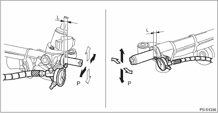
 Installation
1. Before installation, check the steering gearbox. Electric Power Steering Gearbox > INSPECTION2. Install the steering gearbox assembly by tightening the bolts through the stiffener to the specified ...
 Disassembly
CAUTION:When fixing the steering gearbox assembly in a vise, apply a wooden piece on the flange portion.1. Remove the tie-rod end (a) and lock nut (b) from the steering gearbox assembly.2. Remove the ...
Other materials:
Diagnostics chart for security indicator light inspection
1. CHECK SECURITY INDICATOR LIGHT CIRCUITCAUTION:When the body integrated unit (except for C0 and C5 models) or the immobilizer CM (C0 and C5 models) is replaced, registration of the immobilizer system is required. For details, refer to the “REGISTRATION MANUAL FOR IMMOBILIZER” provided ...
