Subaru Legacy BN/BS (2015-2019) Service Manual: Installation
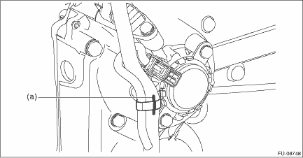
1. Set the engine wiring harness to the engine, and connect the connector. NOTE: • If the clip is damaged, replace it with a new part. • Before replacing the clip, put an alignment mark (a) on both engine wiring harness and clip to remove the clip, and then align to the alignment mark (a) to attach a new clip to the engine wiring harness.
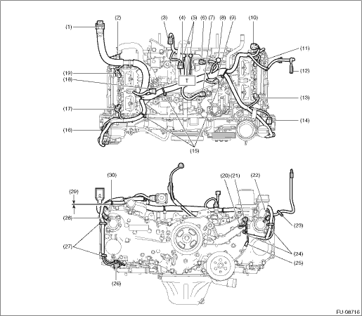
• Structural diagram 1
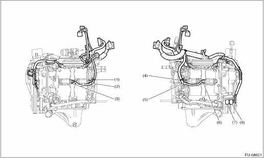
• Structural diagram 2
2. Install the intake manifold assembly. Intake Manifold Assembly > INSTALLATION 3. Connect the ground terminal to battery sensor. NOTE | |||||||||||||||||||||||||||||||||||||||||||||||||||||||||||||||||||||||||||||||||||||||||||||||||||||||||||||||||||||||||||
 Inspection
Check that the engine wiring harness does not have deformation, cracks and any other damage. ...

Other materials:
AT OIL TEMP warning light (CVT models)
If this light illuminates when the engine is
running, it may indicate that the transmission
fluid temperature is too hot.
If the light illuminates while driving, immediately
stop the vehicle in a safe place
and let the engine idle until the warning
light turns off.
Transmission control syst ...
